
Related Manuals for ESAB ES 150i


Summary of Contents for ESAB ES 150i
- Page 1 ES 150i, ES 180i, ES 180i Pro, ES 200i Pro, ET180i, ET 200iP, ET 200iP Pro Service manual Valid for: Serial No. HA017-, HA018-, HA019-, HA020-, HA026-, HA027-xxxx-xxxx 0463 714 001 GB 20201008...
-
Page 2: Table Of Contents
Installation of MMA ................. ERROR CODES/ERROR DESCRIPTIONS IN THE SERVICE LOG ..Error code descriptions and service technician actions ....WIRING DIAGRAM ................... ES 150i, ES 180i ..................ES 180i Pro, ES 200i Pro ................ ET 180i ..................... ET 200iP .................... - Page 3 Cleaning instruction ................After repair, inspection and test ............Visual inspection ..................Electrical test ..................Functional test ..................Test report ....................SPARE PARTS AND ACCESSORIES ............. Rights reserved to alter specifications without notice. 0463 714 001 © ESAB AB 2020...
-
Page 4: Read This First
The unit is tested by ESAB in a general set-up. The responsibility for safety and function, of the specific set-up, lies with the integrator. The "ES 150i", "ES 180i", "ES 180i Pro", "ES 200i Pro", "ET 180iP", "ET 200iP" and "ET 200iP Pro" are designed and tested in accordance with the standards stated in the instruction manual. - Page 5 READ THIS FIRST CAUTION! STATIC ELECTRICITY can damage circuit boards and electronic components. • Observe precautions for handling electrostatic sensitive devices. • Use proper static-proof bags and boxes. 0463 714 001 - 5 - © ESAB AB 2020...
-
Page 6: Before Starting Service
Follow the instructions in chapter "IN-SERVICE INSPECTION AND TESTING", page 55 when performing service work on the equipment! Service aid ESAB can offer a number of service tools that will simplify the service. Antistatic service kit Ordering no. 0740 511 001 The kit makes it easier to protect sensitive components from electrostatic discharge. -
Page 7: Introduction
INTRODUCTION INTRODUCTION The "ES 150i", "ES 180i", "ES 180i Pro" and "ES 200i Pro" are an inverter-based power sources intended for MMA (Manual Metal Arc) and TIG (Tungsten Inert Gas) welding. The "ET 180i", "ET 200iP" and "ET 200iP Pro" are an inverter-based power sources intended for MMA (Manual Metal Arc), TIG (Tungsten Inert Gas) welding and HF TIG (High Frequency Tungsten Inert Gas) welding. -
Page 8: Welding Equipment
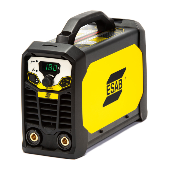
INTRODUCTION Welding equipment ES 150i, ES180i Current display VRD indicator Positive probe Thermal protection indicator Negative probe Current adjusting knob Power cable Welding selection mode button Power switch Plastic front panel 0463 714 001 - 8 - © ESAB AB 2020... - Page 9 Welding mode selection button Power cable Plastic front panel Power switch Aviation socket harness VRD indicator ES 150i, ES 180i, ES 180i Pro, ES 200i Pro Handle Rogue label Left side panel 0463 714 001 - 9 - © ESAB AB 2020...
- Page 10 INTRODUCTION Warning label ESAB label Left side panel Rating plate Bottom panel 0463 714 001 - 10 - © ESAB AB 2020...
- Page 11 INTRODUCTION Rating plates: ES 150i, ES 180i Rating plates: ES 180i Pro, ES 200i Pro 0463 714 001 - 11 - © ESAB AB 2020...
-
Page 12: Installation Of Mma
INTRODUCTION Installation of MMA Connection between Welder and Power Source • ES 150i, ES 180i output voltage is 220-240 VAC, 50/60 Hz • ES 180i Pro, ES 200i Pro output voltage is 90-260 VAC, 50/60 Hz Installation of optional TIG torch Remove the ground cable and the electrode holder from the weld output connections. - Page 13 INTRODUCTION Schematic diagram ES 150i, ES 180i Schematic diagram ES 180i Pro, ES 200i Pro Parts Functions START PROTECTION To avoid equipment breakdown, the power source CONTROL measures the mains voltage when the power switch is turned ON. To protect the power source, check that the mains voltage is correct according to the rating (230 VAC) before switching on the PFC.
- Page 14 Controls the switch for inverter circuit. AUXILIARY POWER SUPPLY Supply power for CONTROL CIRCUIT and DRIVING CIRCUIT. FEEDBACK CIRCUIT Gets sampling from the output, sends feedback to CONTROL CIRCUIT. Power factor correction. 0463 714 001 - 14 - © ESAB AB 2020...
-
Page 15: Error Codes/Error Descriptions In The Service Log
"TROUBLESHOOTING", page 44 E01 Thermal protection Turn off the mains power supply to reset the unit. If the error persists, take actions according to Troubleshooting procedures. 0463 714 001 - 15 - © ESAB AB 2020... -
Page 16: Wiring Diagram
Converts AC to DC. Electrolytic capacitor Smooths the DC voltage. Inverter circuit IGBT Converts low frequency DC to 48 kHz high frequency AC. Main transformer Converts HF high voltage to HF low voltage power. 0463 714 001 - 16 - © ESAB AB 2020... - Page 17 Converts HF AC to HF DC power. NOTE! IGBT and FRD look very similar. Read the descriptions carefully before you do repair to make sure you do not use the wrong part. 0463 714 001 - 17 - © ESAB AB 2020...
-
Page 18: 150I, Es 180I
WIRING DIAGRAM ES 150i, ES 180i Valid from serial number: HA017-xxxx-xxxx, HA018-xxxx-xxxx 0463 714 001 - 18 - © ESAB AB 2020... -
Page 19: 180I Pro, Es 200I Pro
WIRING DIAGRAM ES 180i Pro, ES 200i Pro Valid from serial number: HA019-xxxx-xxxx, HA020-xxxx-xxxx 0463 714 001 - 19 - © ESAB AB 2020... - Page 20 WIRING DIAGRAM Valid from serial number: HA019-xxxx-xxxx, HA020-xxxx-xxxx 0463 714 001 - 20 - © ESAB AB 2020...
-
Page 21: 180I
WIRING DIAGRAM ET 180i From serial number HA026-xxxx-xxxx 0463 714 001 - 21 - © ESAB AB 2020... -
Page 22: 200Ip
WIRING DIAGRAM ET 200iP From serial number HA027-xxxx-xxxx 0463 714 001 - 22 - © ESAB AB 2020... -
Page 23: 200Ip Pro
WIRING DIAGRAM ET 200iP Pro From serial number HA027-xxxx-xxxx 0463 714 001 - 23 - © ESAB AB 2020... -
Page 24: Components Description
WIRING DIAGRAM Components description ES 150i, ES 180i EMC PCB Output rectifier PCB Control panel PCB Secondary diode 0463 714 001 - 24 - © ESAB AB 2020... - Page 25 WIRING DIAGRAM Main PCB IGBT Main PCB Main transformer 0463 714 001 - 25 - © ESAB AB 2020...
- Page 26 NTC connector Drive transformer Main relay Auxiliary transformer Fan connector IGBT Heat-Sink Connector between front PCB and Capacitors inverter PCB Voltage feedback connector PCB Inverter PCB board - back view 0463 714 001 - 26 - © ESAB AB 2020...
- Page 27 Power connection (310V), pins in the IGBT Heat-Sink CN1 connector is 4.3.2.1 (from right to left) Rectifier PCB board Main transformer Main transformer primary input connector Secondary diode radiator Main transformer primary input connector 0463 714 001 - 27 - © ESAB AB 2020...
-
Page 28: 180I Pro, Es 200I Pro
WIRING DIAGRAM ES 180i Pro, ES 200i Pro EMC PCB Output rectifier PCB Control panel PCB Secondary diode 0463 714 001 - 28 - © ESAB AB 2020... - Page 29 WIRING DIAGRAM Main PCB IGBT Connection line Main transformer 0463 714 001 - 29 - © ESAB AB 2020...
- Page 30 WIRING DIAGRAM PFC electrical inductance Output rectifier PFC, PCB board 0463 714 001 - 30 - © ESAB AB 2020...
- Page 31 Drive transformer Fan connector Auxiliary transformer Connector between front PCB and IGBT Heat-Sink inverter PCB Aviation socket harness connector Capacitors Voltage feedback connector PCB inverter PCB board - back view 0463 714 001 - 31 - © ESAB AB 2020...
- Page 32 Power connection (310V), pins in the IGBT heat-sink CN1 connector is 4.3.2.1 (from right to left) Rectifier PCB board Main transformer Main transformer primary input connector Secondary diode radiator Main transformer primary input connector 0463 714 001 - 32 - © ESAB AB 2020...
-
Page 33: 180I, Et 200Ip, Et 200Ip Pro
WIRING DIAGRAM ET 180i, ET 200iP, ET 200iP PRO Control panel PCB EMC PCB HF board 0463 714 001 - 33 - © ESAB AB 2020... -
Page 34: Technical Data
TECHNICAL DATA TECHNICAL DATA ES 150i, ES 180i Technical data Rogue ES 180i Rogue ES 150i Outlet voltage 230 V±15% 230 V±15% 1~ 50/60 Hz 1~ 50/60 Hz Primary current 36 A 30 A Live TIG 24 A 18.5 A No-load power demand when in energy saving mode 30 W 30 W Setting range 20-180 A... -
Page 35: 180I Pro, Es 200I Pro
TECHNICAL DATA Rogue ES 180i Rogue ES 150i Transportation temperature -20 to +55 °C -20 to +55 °C (-4 to +131 °F) (-4 to +131 °F) Continual sound pressure at <70 dB <70 dB no-load Dimensions l × w × h 403×153×264 mm 403×153×264 mm (15.8 × 6 × 10.4 in.) (15.8 × 6 × 10.4 in.) Weight 6.8 kg 6.8 kg Insulation class transformer... - Page 36 (-4 to +131 °F) Continual sound <70 dB <70 dB <70 dB <70 dB pressure at no-load Dimensions 403×153×264 mm 403×153×264 mm l × w × h (15.8×6×10.4 in.) (15.8×6×10.4 in.) Weight 8.4 kg 8.4 kg Insulation class transformer Enclosure IP23 IP23S class Application class 0463 714 001 - 36 - © ESAB AB 2020...
-
Page 37: 180I
VRD 35 V activated <30 V Operating temperature -10 to +40 °C (+14 to 104 °F) Transportation temperature -20 to +55 °C (-4 to +131 °F) Continual sound pressure at no-load <70 dB Dimensions l × w × h 403 × 153 × 264 mm (15.9 × 6 × 10.4 in.) Weight 8.7 kg 0463 714 001 - 37 - © ESAB AB 2020... - Page 38 TECHNICAL DATA Rogue ET 180i Insulation class transformer Enclosure class IP23S Application class 0463 714 001 - 38 - © ESAB AB 2020...
-
Page 39: 200Ip
VRD 35 V activated <30 V Operating temperature -10 to +40 °C (+14 to 104 °F) Transportation temperature -20 to +55 °C (-4 to +131 °F) Continual sound pressure at no-load <70 dB Dimensions l × w × h 403 × 153 × 264 mm (15.9 × 6 × 10.4 in.) Weight 8.7 kg 0463 714 001 - 39 - © ESAB AB 2020... -
Page 40: 200Ip Pro
Efficiency at maximum current Live TIG Open-circuit voltage U VRD 35 V deactivated 78 V 78 V VRD 35 V activated <30 V <30 V Operating temperature -10 to +40 °C -10 to +40 °C (+14 to 104 °F) (+14 to 104 °F) 0463 714 001 - 40 - © ESAB AB 2020... - Page 41 Equipment marked IP23 is intended for indoor and outdoor use. Application class The symbol indicates that the power source is designed for use in areas with increased electrical hazard. 0463 714 001 - 41 - © ESAB AB 2020...
-
Page 42: Panel Operation Instructions
V1.0 CHS number (channel) appears. Release the S4 button. • Adjust the EC11 encoder, choose 10 channel for ES 150i or 13 channel for ES 180i. Then press and hold the S4 button until the SdJ number appears. Release the S4 button. -
Page 43: Vrd On And Off
The default setting of VRD is OFF, the VRD light is off. Under MMA mode, the output voltage for ES 150i, ES 180i is 63V±5%, for ES 180i, ES 200i PRO is 78V±5%. 0463 714 001 - 43 - © ESAB AB 2020... -
Page 44: Troubleshooting
Connect the negative probe to DC + and positive probe to DC -, it should read 0.85±0.2V. Negative and positive probe each connected to AC -, it should read 0.47V±0.05V. Connect positive probe to DC -, and negative probe to AC -, it should read 0.47V±0.05V. 0463 714 001 - 44 - © ESAB AB 2020... - Page 45 0.26V. When changed in the opposite direction, it should be infinitely high. Overload protection The yellow light on the panel is on. Digital display shows E01. The power source will return to normal when it cools down. 0463 714 001 - 45 - © ESAB AB 2020...
-
Page 46: Restoring The Power Source After Pre Power Up Checks
Power up checks After having performed pre power up checks according to the instructions in the previous pages and restored the power source you can perform power up check as follows: 0463 714 001 - 46 - © ESAB AB 2020... - Page 47 TROUBLESHOOTING Position voltage and waveform test PCB Power voltage test Switch to MMA mode to test the switch power voltage. Open circuit voltage 0463 714 001 - 47 - © ESAB AB 2020...
- Page 48 Voltage of CN201 pin 2 is 24V (GND is pin 4 of CN301), If the voltage is abnormal, then the input power or main board might be defect. Replace the PCB. 0463 714 001 - 48 - © ESAB AB 2020...
- Page 49 Reinsert or replace the connecting wire between main board display is and front panel control PCB. If the fault persists continue to Step 2. adjustable. Step 2: Replace the front panel control PCB. 0463 714 001 - 49 - © ESAB AB 2020...
- Page 50 Step 2: If the main relay on the main control panel is not working, and the driving is abnormal, the power source will not work. Replace the main control PCB. 0463 714 001 - 50 - © ESAB AB 2020...
- Page 51 ES 200i Pro). Reinsert or replace the control line which connects the PFC board and the inverter board. If the fault persists continue to Step 2. Step 2: Replace the PFC board. 0463 714 001 - 51 - © ESAB AB 2020...
-
Page 52: Advanced Measurements
IGBT (Q1-Q4) GE drive waveform test The drive frequency is 48±3 kHz. Drive frequency is 48 kHz, the amplitude is about 15V. Main transformer secondary waveform test The no-load voltage is normal. 0463 714 001 - 52 - © ESAB AB 2020... - Page 53 TROUBLESHOOTING Troubleshooting with mains voltage - Remote equipment signals 0463 714 001 - 53 - © ESAB AB 2020...
- Page 54 TROUBLESHOOTING Troubleshooting with mains voltage - Current sensor 0463 714 001 - 54 - © ESAB AB 2020...
-
Page 55: In-Service Inspection And Testing
Make sure that the cleaning procedure is done in a suitable prepared workspace. CAUTION! During cleaning, always wear recommended personal safety equipment, such as ear plugs, safety glasses, masks, gloves and safety shoes. 0463 714 001 - 55 - © ESAB AB 2020... -
Page 56: After Repair, Inspection And Test
The inspection and test shall be documented in a test report (see section "Test report", page 60) A signed and dated label shall be attached to the equipment after an approved test. 0463 714 001 - 56 - © ESAB AB 2020... -
Page 57: Visual Inspection
○ cooling liquid circuit leakage or incorrect cooling liquid level ○ defective gas hoses and connections ○ poor legibility of markings and labelling ○ other damage or signs of improper use 0463 714 001 - 57 - © ESAB AB 2020... -
Page 58: Electrical Test
Required value: 2.5 MΩ or more Turn the welding power source mains switch to position OFF. Check the no-load voltage, using the ESAB test box TB 1. If the welding power source has an activated VRD function, proceed to item 5 below instead. -
Page 59: Functional Test
Disconnect the welding power source from the mains supply. Write the test report (see section "Test report", page 60). If the unit passes all tests, attach the appropriate label containing signature and date of the test. 0463 714 001 - 59 - © ESAB AB 2020... -
Page 60: Test Report
• Input circuit/Protective ≥ 2.5 MΩ circuit (500 V No-load voltage: • without VRD ≤113 V peak • with VRD activated ≤35 V peak Electrical test Passed □ FUNCTIONAL TEST Passed □ Remarks 0463 714 001 - 60 - © ESAB AB 2020... - Page 61 IN-SERVICE INSPECTION AND TESTING Date Tested by Signature Testing company 0463 714 001 - 61 - © ESAB AB 2020...
-
Page 62: Spare Parts And Accessories
Product Spare parts list 0463 720 001 ES 150i, ES 180i, ES 180i Pro, ES 200i Pro Instruction manual 0463 732 * ES 150i, ES 180i Instruction manual 0463 710 * ES 180i Pro, ES 200i Pro Instruction manual 0463 752 * ET 180iP Instruction manual... - Page 63 SPARE PARTS AND ACCESSORIES 0463 714 001 - 63 - © ESAB AB 2020...
- Page 64 For contact information visit esab.com ESAB AB, Lindholmsallén 9, Box 8004, 402 77 Gothenburg, Sweden, Phone +46 (0) 31 50 90 00 http://manuals.esab.com...
Need help?
Do you have a question about the ES 150i and is the answer not in the manual?
Questions and answers