Table of Contents
Advertisement
Quick Links
Discontinue
INSTRUCTION
MANUAL
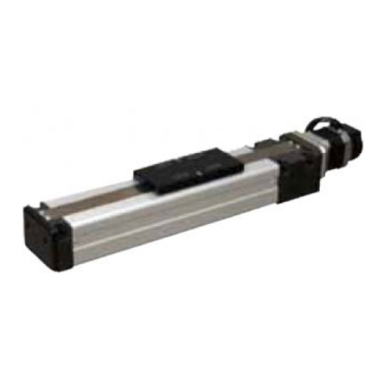
ELECTRIC ACTUATOR
KBZ Series
SLIDER TYPE
TABLE TYPE
KBZ-5D
KBZ-7D
ACTUATOR INSTRUCTION
MANUAL
● Read this manual carefully and thoroughly
before using this product.
● Pay extra attention to the instructions
concerning safety.
● After reading this manual, keep it in a safe
and convenient place.
1
SM-479502-A
Advertisement
Table of Contents

Related Manuals for CKD KBZ Series


Summary of Contents for CKD KBZ Series
- Page 1 Discontinue SM-479502-A INSTRUCTION MANUAL ELECTRIC ACTUATOR KBZ Series SLIDER TYPE TABLE TYPE KBZ-5D KBZ-7D ACTUATOR INSTRUCTION MANUAL ● Read this manual carefully and thoroughly before using this product. ● Pay extra attention to the instructions concerning safety. ● After reading this manual, keep it in a safe...
-
Page 2: Introduction
All efforts have been made to assure the contents of this manual. If you have any questions, or find any mistakes, however, please contact CKD. CKD will not be held responsible for any effects caused by using this equipment, regardless of Item 3 above. -
Page 3: Table Of Contents
Discontinue Table of Contents Page Introduction 2 General Descriptions ..................... 1 Section 1 Safety ......................1 Safety Instructions ..................1 To Use the Equipment Safely ................ 5 1.2.1 Safety Measures ................5 1.2.2 Installation Precautions ..............5 1.2.3 Usage Precautions ................6 Warranty ...................... - Page 4 Discontinue Replacing Stainless Sheet and Slide Table ..........27 Lubricating Each Part .................. 27 Maintenance of Other Parts ................. 28 5.10 Clamping Torque of Bolts and Nuts ............. 28 Section 6 Spare Parts ....................29 Spare Parts....................29...
-
Page 5: General Descriptions
After you have read this manual, keep it nearby for future reference. Be sure to strictly observe the following safety instructions to assure correct use of the Electric Actuator KBZ series. This manual contains the important information to prevent injury to the operators and persons nearby, to prevent damage to assets and to assure correct use of the equipment. - Page 6 Discontinue WARNING • Install the safety fences to prevent anyone from entering the working envelope of the robot. When the door is attached to the safety fence, the robot should be stopped at emergency at the same time that the door has opened. •...
- Page 7 Discontinue • DO NOT use this equipment for the living body as a massaging machine. Otherwise, you will be injured due to incorrect teaching or mis-operation. • This equipment is not completely sealed. During use, grease or wear of resin may scatter from the opening of the equipment.
- Page 8 Discontinue CAUTION • DO NOT place the equipment at a place where the ambient temperature exceeds 40°C, or where the temperature changes sharply, causing condensing, or where it is exposed to direct sunlight. DO NOT place it at a narrow place, either. Otherwise, the ambient temperature rises due to heat generation in the controller itself or external device, which will result in malfunction or mis-operation of the equipment.
-
Page 9: To Use The Equipment Safely
Discontinue To Use the Equipment Safely Before using the Electric Actuator KBZ Series, measures must be taken that meet the requirements below. This equipment corresponds to an industrial robot as stipulated in Article 36, Item 31 of the Occupational Safety and Health Rules. In accordance with Article 28 of the Occupational Safety and Health Law, important information needed for “Selection”, “Installation”, “Operation”, “Periodic Inspection”, and... -
Page 10: Usage Precautions
Discontinue 1.2.3 Usage Precautions Pay attention to the following points in usage of the robot. [Work within the movement range] (1) Work rules Rules must be established for the items below, and work must be performed in accordance with these rules. Startup procedures, switch operating procedures, and other robot operation methods and procedures required in the work Robot unit speed when performing the teaching operation... -
Page 11: Warranty
(1) This warranty covers this product. The scope of the warranty applies to the specifications and functions that were stipulated in the specifications, catalog, instruction manual, and other documentation of this product. CKD will not be liable for any secondary or incidental damage as a result of breakdowns of this product. -
Page 12: Disclaimers
(1) CKD cannot guarantee basic performance of this product when it is used under conditions outside the product specifications. (2) CKD is not liable for any accidents, damage, or breakdowns that occur as a result of failing to follow the warning and caution information provided in this instruction manual. -
Page 13: Type Of Axis And Name Of Each Part
Discontinue Section 3 Axis (Actuator) Specifications Type of Axis and Name of Each Part • Type of axis The type of axis is as shown below. KBZ -5 D - ST - M 12 N - 30 Series name Axis stroke (Note 2) Lead of ball screw 50 mm Type of axis... -
Page 14: Single Axis Specifications
Discontinue Single Axis Specifications Specifications (Slider Type) Type of axis: KBZ–5D–ST–M□□□–□□ Motor 50 W AC servo motor Use of ball screw Drive system Diameter 8 mm Lead 12 mm, 6 mm Guide system Linear guide (rail, block (1 each)) Horizont Lead of ball screw Vertical Maximum... - Page 15 Discontinue Note 1: The numbers in parentheses ( ) are the values when a regenerative discharge resistor (CAR-0500) or regenerative discharge unit (CAR-UN50) is installed. Note 2: The maximum speed varies depending on the stroke specifications. For the 500 mm specifications, the maximum speed is 630 mm/s.
- Page 16 Discontinue Specifications (Table Type) Type of axis: KBZ–5D–ST–T□□□–□□ Motor 50 W AC servo motor Use of ball screw Drive system Diameter 8 mm Lead 12 mm, 6 mm Guide system Linear guide (rail, block (1 each)) Lead of ball screw Stroke Horizontal Vertical...
- Page 17 Discontinue Note 1: The numbers in parentheses ( ) are the values when a regenerative discharge resistor (CAR-0500) or regenerative discharge unit (CAR-UN50) is installed. Note 2: This is the allowable value of the moment that can be applied to the table end section. MR: Rolling moment MP: Pitching moment MY: Yawing moment...
- Page 18 Discontinue Axis dimensions [KBZ–5D–ST–M**] (50 W motor specifications)
- Page 19 Discontinue [KBZ–7D–ST–M**] (50 W motor specifications)
- Page 20 Discontinue [KBZ–5D–ST–T**] (50 W motor specifications)
- Page 21 Discontinue [KBZ–7D–ST–T**] (50 W motor specifications)
-
Page 22: Installing Actuator (Axis)
Discontinue Section 4 Installing Actuator (Axis) Installing Actuator (Axis) • This section describes the basic installation of the actuator (axis) and basic mounting of the peripheral parts. • Install the actuator, referring to this section. If the actuator is installed incorrectly, the robot cannot be operated to its full capacity and its service life will shorten drastically. -
Page 23: Setting Type Of Robot
Discontinue Setting Type of Robot The type of the robot refers to a six (6)-digit numerical number specified according to the type of the axis (actuator). Once the type of the robot has been specified, various parameter values for the axis (actuator) to be used are set automatically. -
Page 24: Parameter 2 Assigned By Type Of Robot
Discontinue 4.3.2 Parameter 2 Assigned by Type of Robot Compared to Parameter 1, this includes axis-related parameters that are changed less frequently. After these parameters are changed, be sure to turn the control power and drive power off and then on again. -
Page 25: Inspection Before Starting Operation
Discontinue Before disassembling the air pressure gage, etc., or replacing the part, release the residual pressure from the cylinder. When disassembling the hydraulic or pneumatic circuit or replacing the part, take utmost care not to allow adhesion or entry of contaminant. Measures to be taken at the end of inspection and maintenance Persons in charge of inspection and maintenance should return all tools to the predetermined place after the work has finished. -
Page 26: Adjusting Home Position
Discontinue Adjusting Home Position Adjust the home position in the following manner. Place the axis in a horizontal location, and turn off the power. (When a brake is installed, check that the servo is off.) Loosen and remove the two Phillips-head screws from the top side of the motor block. Remove these two Phillips-head screws. -
Page 27: Changing Home Position
Discontinue Execute the home return. After the motor has stopped, move the slider end manually to the position "A" mm away from the motor block end surface. (See Fig. 5.4–3.) Upon the execution of the home return operation, this equipment stops once each time the motor makes a half turn. -
Page 28: Replacing Motor And Changing Motor Lead Wire Hole Direction
Discontinue Replacing Motor and Changing Motor Lead Wire Hole Direction When replacing the motor or changing the direction of the motor lead wire hole, observe the following procedures. Place the axis in a horizontal location, and turn off the power. (When a brake is installed, check that the servo is off.) Loosen and remove the two Phillips-head screws from the top side of the motor block. - Page 29 Discontinue (7-1) [For the KBZ-5D-ST] Joint shaft Coupling Motor Loosen the hexagon socket cap screw. Fig. 5.6–4 Loosen the hexagon socket cap screw (M2) joining the coupling and joint shaft. (8-1) Connect the motor unit with joint shaft (new motor with joint shaft if replacing the motor) and controller, and turn on the power.
- Page 30 Discontinue (9-2) Perform the home position return operation, and after the motor is stopped, insert the coupling into the motor shaft. When assembling the motor (if changing the direction that the motor wire comes out, remove the Phillip-head countersunk screw, rotate the motor, and tighten to the motor bracket), perform positioning so that the coupling screw is visible from the motor block opening.
-
Page 31: Replacing Stainless Sheet And Slide Table
Discontinue Replacing Stainless Sheet and Slide Table To replace the stainless sheet, observe the following procedures. Take careful precautions not to cut your hand by the stainless sheet. CAUTION Remove the four (4) screws securing the stainless sheet, using a screwdriver, and remove the plate. -
Page 32: Maintenance Of Other Parts
Discontinue Lubricating point Type of oil Lubricating Lubricating volume (Maker) intervals Alvania grease S2 Every three (3) Apply a thin coat of oil to the ball Ball screw (Shell Oil) months screw. Fill the oil of about 1 cc from Linear guide grease nipples. -
Page 33: Spare Parts
For KBZ-5D-ST-M KBZ-5D-ST-T Slide table For KBZ-7D-ST-M KBZ-7D-ST-T For KBZ-7D-ST-M KBZ-7D-ST-T (50 W) AC servo motor (Resolver) (used for all KBZ series models) AC servo motor with brake For KBZ-7D-ST-M KBZ-7D-ST-T (50 W) (Resolver) (used for all KBZ series models)
Need help?
Do you have a question about the KBZ Series and is the answer not in the manual?
Questions and answers