Table of Contents

Related Manuals for IEI Technology IVCE-C604


Summary of Contents for IEI Technology IVCE-C604
- Page 1 IVCE-C608/IVCE-C604/IVCME-C604 Capture Card IEI Technology Corp. MODEL: IVCE-C608/IVCE-C604/IVCME-C604 Video Capture Card with PCIe/PCIe Mini Interface 8-Channel/4-Channel Input, RoHS Compliant User Manual Page 1 Rev. 1.00 – 6 February, 2012...
- Page 2 IVCE-C608/IVCE-C604/IVCME-C604 Capture Card Revision Date Version Changes 6 February, 2012 1.00 Initial release Page 2...
- Page 3 IVCE-C608/IVCE-C604/IVCME-C604 Capture Card Copyright COPYRIGHT NOTICE The information in this document is subject to change without prior notice in order to improve reliability, design and function and does not represent a commitment on the part of the manufacturer. In no event will the manufacturer be liable for direct, indirect, special, incidental, or consequential damages arising out of the use or inability to use the product or documentation, even if advised of the possibility of such damages.
-
Page 4: Table Of Contents
2.1.4 System Requirements..................19 2.1.5 Mechanical and Environmental Specifications..........20 2.2 D ......................21 IMENSIONS 2.2.1 IVCE-C608 Dimension Drawing ..............21 2.2.2 IVCE-C604 Dimension Drawing ..............22 2.2.3 IVCME-C604 Dimension Drawing..............23 3 PACKING LIST ......................24 3.1 A ..................25 STATIC RECAUTIONS 3.2 U... - Page 5 4.1.2.1 IVCE-C604 Switch (SW1) ................. 7 4.1.2.2 IVCE-C604 LED Screen (LED2) ............... 7 4.1.2.3 IVCE-C604 LED Indicators (LED1) ............7 4.1.2.4 IVCE-C604 Reset Input Connector (CN4) ..........8 4.1.2.5 IVCE-C604 Reset Output Connector (CN5) ..........8 4.1.2.6 IVCE-C604 Video/Audio Input/Output Connector (J1) ......8 4.1.2.7 IVCE-C604 GPIO Connector (CN3) ............
- Page 6 IDEO APTURE UITE 6.3.1 Video Capture....................34 6.3.2 Video Bypass (IVCE-C608 and IVCE-C604 Only) .......... 40 6.3.3 Video Out (IVCE-C608 and IVCE-C604 Only) ..........42 6.3.4 Other Functions ....................44 6.3.4.1 Frame Rate ....................45 6.3.4.2 Color Control .................... 46 6.3.4.3 GPIO ......................
- Page 7 Figure 2-3: IVCME-C604 Dimension Drawing ................23 Figure 4-1: IVCE-C608 Connectors and Pinouts (pin numbers in red) ........3 Figure 4-2: IVCE-C604 Connectors and Pinouts (pin numbers in red) ........7 Figure 4-3: IVCME-C604 Connectors and Pinouts (pin numbers in red) ........10 Figure 5-1: IVCE-C608 and IVCE-C604 Installation ..............16 Figure 5-2: Cascade Reset Connection..................17...
- Page 8 IVCE-C608/IVCE-C604/IVCME-C604 Capture Card Figure 6-11: Uninstall IEI Video Capture Test Suite (Start Menu)..........33 Figure 6-12: Device Manager – Uninstall Driver ................34 Figure 6-13: IEI Video Capture Test Suite ..................35 Figure 6-14: Available Cards .......................36 Figure 6-15: Capture Settings Window..................36 Figure 6-16: Audio Preview Selection ..................38 Figure 6-17: Recording File Path Selection ................39...
- Page 9 Table 4-6: IVCE-C604 Connectors....................6 Table 4-7: IVCE-C604 Reset Input Connector Pinouts..............8 Table 4-8: IVCE-C604 Reset Output Connector Pinouts.............8 Table 4-9: IVCE-C604 Video/Audio Input Connector Pinouts ............9 Table 4-10: IVCE-C604 GPIO Connector Pinouts ................9 Table 4-11: IVCME-C604 Connectors..................10 Table 4-12: IVCME-C604 Video/Audio Input Connector Pinouts ..........11 Table 4-13: IVCME-C604 GPIO Connector Pinouts ..............11...
-
Page 10: Introduction
IVCE-C608/IVCE-C604/IVCME-C604 Capture Card Chapter Introduction Page 10... -
Page 11: Overview
IVCE-C608/IVCE-C604/IVCME-C604 Capture Card 1.1 Overview Figure 1-1: IVCE-C608/IVCE-C604/IVCME-C604 Capture Cards The low power IVCE-C608/IVCE-C604/IVCME-C604 video capture cards are essential surveillance system components. The IVCE-C608/IVCE-C604/IVCME-C604 video capture cards are equipped with the high-performing Conexant video capture controllers with up to eight video and audio input channels. -
Page 12: Model Variations
PCIe Mini 4 channels 4 channels IVCME-C604 Table 1-1: IVCE-C608/IVCE-C604/IVCME-C604 Video Capture Card Models 1.1.2 Features Some of the IVCE-C608/IVCE-C604/IVCME-C604 video capture card features are listed below. Low power Multiple card support Easy ID programming PCIe/PCIe Mini connection interface Software development kit (SDK) Demo application 1.1.3 Software Support... -
Page 13: Overview Photo
IVCE-C608/IVCE-C604/IVCME-C604 Capture Card 1.2 Overview Photo The IVCE-C608/IVCE-C604/IVCME-C604 video capture cards have a wide variety of peripheral interface connectors. The following sections give an overview of each model. 1.2.1 IVCE-C608 Overview The IVCE-C608 comes with one Conexant CX25853 video capture controller, two GPIO connectors, one rotary switch, LED indicators and one DB-26 video/audio connector. -
Page 14: Ivce-C604 Overview
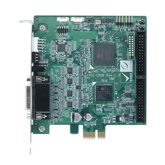
LED indicators and one DB-26 video/audio connector. A PCIe edge connector on the bottom of the capture card enables the IVCE-C604 to interface with a motherboard or CPU card. An overview can be seen in Figure 1-3: IVCE-C604 Overview. -
Page 15: Ivcme-C604 Overview
IVCE-C608/IVCE-C604/IVCME-C604 Capture Card 1.2.3 IVCME-C604 Overview The IVCME-C604 comes with one Conexant CX25854 video capture controller, one GPIO connector and one video/audio connector. The PCIe Mini interface of the capture card enables the IVCME-C604 to interface with a motherboard. An overview can be seen in Figure 1-4: IVCME-C604 Overview. -
Page 16: Product Specifications
IVCE-C608/IVCE-C604/IVCME-C604 Capture Card Chapter Product Specifications Page 16... -
Page 17: Specifications
IVCE-C608/IVCE-C604/IVCME-C604 Capture Card 2.1 Specifications The following specifications are listed in the tables below: Table 2-1: Video Interfaces Table 2-2: Video Processing Table 2-3: Audio Processing Table 2-4: System Requirements Table 2-5: Mechanical and Environmental Specifications 2.1.1 Video Interfaces The following table lists detailed specifications for the interfaces on the three video capture cards. -
Page 18: Video Processing
IVCE-C608/IVCE-C604/IVCME-C604 Capture Card 2.1.2 Video Processing The following table lists detailed specifications for the video processing features on the three video capture cards. VIDEO PROCESSING IVCE-C608 IVCE-C604 IVCME-C604 Video Compression Software compression Software compression Software compression Video Engine One Conexant CX25853... -
Page 19: Audio Processing
IVCE-C608/IVCE-C604/IVCME-C604 Capture Card 2.1.3 Audio Processing The following table lists detailed specifications for the audio processing features on the three video capture cards. AUDIO PROCESSING IVCE-C608 IVCE-C604 IVCME-C604 Audio Compression Software compression Software compression Software compression 8 kHz 32 kHz... -
Page 20: Mechanical And Environmental Specifications
IVCE-C608/IVCE-C604/IVCME-C604 Capture Card 2.1.5 Mechanical and Environmental Specifications The following table lists the dimensions, operating temperature and power consumption for each model. OTHERS IVCE-C608 IVCE-C604 IVCME-C604 Dimensions (mm) 111.00 x 102.40 111.23 x 102.39 50.92 x 30.00 -5ºC – 65ºC, -5ºC –... -
Page 21: Dimensions
IVCE-C608/IVCE-C604/IVCME-C604 Capture Card 2.2 Dimensions The dimensions for each model are listed in Table 2-5: Mechanical and Environmental Specifications above. Detailed dimension drawings for each model are shown in the sections below. 2.2.1 IVCE-C608 Dimension Drawing The dimensions for the IVCE-C608 are listed below: Length: 111.0 mm... -
Page 22: Ivce-C604 Dimension Drawing
IVCE-C608/IVCE-C604/IVCME-C604 Capture Card 2.2.2 IVCE-C604 Dimension Drawing The dimensions for the IVCE-C604 are listed below: Length: 111.23 mm Width: 102.39 mm The dimensions are shown in Figure 2-2: IVCE-C604 Dimension Drawing. Figure 2-2: IVCE-C604 Dimension Drawing Page 22... -
Page 23: Ivcme-C604 Dimension Drawing
IVCE-C608/IVCE-C604/IVCME-C604 Capture Card 2.2.3 IVCME-C604 Dimension Drawing The dimensions for the IVCME-C604 are listed below: Length: 50.92 mm Width: 30.00 mm The dimensions are shown in Figure 2-3: IVCME-C604 Dimension Drawing. Figure 2-3: IVCME-C604 Dimension Drawing Page 23... -
Page 24: Packing List
IVCE-C608/IVCE-C604/IVCME-C604 Capture Card Chapter Packing List Page 24... -
Page 25: Anti-Static Precautions
Only handle the edges of the PCB: Don't touch the surface of the motherboard. Hold the motherboard by the edges when handling. 3.2 Unpacking Precautions When the IVCE-C608/IVCE-C604/IVCME-C604 is unpacked, please do the following: Follow the antistatic guidelines above. Make sure the packing box is facing upwards when opening. -
Page 26: Packing List
Contact the IEI reseller or vendor the IVCE-C608/IVCE-C604/IVCME-C604 was purchased from or contact an IEI sales representative directly by sending an email to ales@iei.com.tw. The IVCE-C608/IVCE-C604/IVCME-C604 is shipped with the following components: Quantity Item and Part Number Image... -
Page 27: Table 3-1: Packing List
Item and Part Number Image Video input cable DB-9 to 4-channel BNC connector (IVCME-C604 only) Audio input cable DB-9 to 4-channel RCA connector (IVCME-C604 only) Reset cable (IVCE-C608 and IVCE-C604 only) Utility CD Quick installation guide Table 3-1: Packing List Page 27... -
Page 28: Optional Items
The following items are optional: Item and Part Number Image 8-channel GPIO card (four digital output and four relay output) (P/N: VIOCARD-GPIO-RS-R10) GPIO cable (for IVCE-C608 and IVCE-C604) (P/N: 32200-000012-RS) GPIO cable (for IVCME-C604) (P/N: 32031-000100-100-RS) Table 3-2: Optional Items Page 28... -
Page 29: Connectors And Jumpers
IVCE-C608/IVCE-C604/IVCME-C604 Capture Card Chapter Connectors and Jumpers Page 29... -
Page 30: Video Capture Card Connector Diagrams
IVCE-C608/IVCE-C604/IVCME-C604 Capture Card 4.1 Video Capture Card Connector Diagrams The connector diagrams for both models are shown in the sections below: 4.1.1 IVCE-C608 Pinouts WARNING: The other connectors, jumpers and interfaces on the board not specified below are for R&D diagnostic purposes and should not be used by the end user. -
Page 31: Ivce-C608 Switch (Sw1)
IVCE-C608/IVCE-C604/IVCME-C604 Capture Card Figure 4-1: IVCE-C608 Connectors and Pinouts (pin numbers in red) 4.1.1.1 IVCE-C608 Switch (SW1) Use the 16-position rotary switch (SW1) to set the ID for the board. Up to 16 IVCE-C608 can be installed in a single system. Each card must be allocated a unique ID. Switch ID settings are explained in more detail in Section 5.4.5. -
Page 32: Ivce-C608 Reset Input Connector (Cn4)
IVCE-C608/IVCE-C604/IVCME-C604 Capture Card Green: self-defined Red: self-defined 4.1.1.4 IVCE-C608 Reset Input Connector (CN4) Use the reset input connector (CN4) to connect to the reset button of the system chassis to enable the multiple card cascade reset function. Pinouts for the connector are shown in Table 4-2. -
Page 33: Ivce-C608 Gpio Connector (Cn2, Cn3)
IVCE-C608/IVCE-C604/IVCME-C604 Capture Card Video Output 2 Audio In CH1 Audio In CH2 Audio In CH3 Audio In CH4 Audio In CH5 Audio In CH6 Audio In CH7 Audio In CH8 Table 4-4: IVCE-C608 Video/Audio Input Connector Pinouts Each IVCE-C608 can support up to eight video inputs, eight audio inputs and two video outputs . -
Page 34: Ivce-C604 Pinouts
The other connectors, jumpers and interfaces on the board not specified below are for R&D diagnostic purposes and should not be used by the end user. The IVCE-C604 has the following connectors and interfaces on board: Quantity Connector Name Connector Type... -
Page 35: Ivce-C604 Switch (Sw1)
Figure 4-2: IVCE-C604 Connectors and Pinouts (pin numbers in red) 4.1.2.1 IVCE-C604 Switch (SW1) Use the 16-position rotary switch (SW1) to set the ID for the board. Up to 16 IVCE-C604 can be installed in a single system. Each card must be allocated a unique ID. Switch ID settings are explained in more detail in Section 5.4.5. -
Page 36: Ivce-C604 Reset Input Connector (Cn4)
Table 4-8: IVCE-C604 Reset Output Connector Pinouts 4.1.2.6 IVCE-C604 Video/Audio Input/Output Connector (J1) Compatible cameras connect to the IVCE-C604 through the DB-26 female connector (via the D-SUB to BNC and RCA cable). Pinouts for the connector are shown in Table 4-9. -
Page 37: Ivce-C604 Gpio Connector (Cn3)
Audio In CH4 Table 4-9: IVCE-C604 Video/Audio Input Connector Pinouts Each IVCE-C604 can support up to four video inputs, four audio inputs and two video outputs . If 16 systems are connected together, a total of 64 cameras can be strung together in a single system. -
Page 38: Ivcme-C604 Pinouts
IVCE-C608/IVCE-C604/IVCME-C604 Capture Card 4.1.3 IVCME-C604 Pinouts WARNING: The other connectors, jumpers and interfaces on the board not specified below are for R&D diagnostic purposes and should not be used by the end user. The IVCME-C604 has the following connectors and interfaces on board:... -
Page 39: Ivcme-C604 Video/Audio Input Connector (Cn1)
IVCE-C608/IVCE-C604/IVCME-C604 Capture Card 4.1.3.1 IVCME-C604 Video/Audio Input Connector (CN1) Compatible cameras connect to the IVCME-C604 through the 10-pin wafer connector (via the D-SUB to BNC and RCA cables). Each IVCME-C604 can support up to four video inputs and four audio inputs. Pinouts for the connector are shown in Table 4-9. -
Page 40: Hardware Installation
IVCE-C608/IVCE-C604/IVCME-C604 Capture Card Chapter Hardware Installation Page 12... -
Page 41: Anti-Static Precautions
IVCE-C608/IVCE-C604/IVCME-C604, or any other electrical component is handled, the following anti-static precautions are strictly adhered to. Wear an anti-static wristband: Wearing a simple anti-static wristband can help to prevent ESD from damaging the board. Self-grounding: Before handling the board, touch any grounded conducting material. -
Page 42: Installation Considerations
Turn all power to the IVCE-C608/IVCE-C604/IVCME-C604 off: When working with the IVCE-C608/IVCE-C604/IVCME-C604, make sure that it is disconnected from all power supplies and that no electricity is being fed into the system. Before and during the installation of the IVCE-C608/IVCE-C604/IVCME-C604 DO NOT: Page 14... -
Page 43: System Requirement
Once the steps above have been completed, the hardware installation procedures are complete. 5.4.2 Video Capture Card Installation The IVCE-C608 and IVCE-C604 have a PCIe x1 interface. To install the IVCE-C608 and IVCE-C604IVCE-C608/IVCE-C604/IVCME-C604, please follow the steps below: Step 1: Align the PCIe edge connector on the bottom of the video capture card with the PCIe slot on the system motherboard or a backplane. -
Page 44: Install The Reset Cables (Optional)
Step 0: 5.4.3 Install the Reset Cables (Optional) The IVCE-C608 and IVCE-C604 are shipped with two reset cables to support cascade reset. To install the reset cables, please follow the instructions below. Step 1: Locate the reset input connector on the first video capture card. -
Page 45: Install The Gpio Card (Optional)
Figure 5-2: Cascade Reset Connection 5.4.4 Install the GPIO Card (Optional) The IVCE-C608 and IVCE-C604 support 8-bit GPIO (4-bit input and 4-bit output) via an optional GPIO card. To install the GPIO card, please follow the instructions below. Step 1: Locate the GPIO connector on the video capture card (see Section 1.2). -
Page 46: Gpio Card Pinouts
IVCE-C608/IVCE-C604/IVCME-C604 Capture Card Figure 5-3: GPIO Cable for IVCE-C608 and IVCE-C604 Step 3: Push the cable connector onto the video capture card GPIO connector making sure the pins are correctly aligned. Step 4: Next, connect the GPIO cable connector to the GPIO connector on the GPIO card (CN6).Step 0:... -
Page 47: Set The Rotary Switch Id Settings
IVCE-C608/IVCE-C604/IVCME-C604 Capture Card 5.4.5 Set the Rotary Switch ID Settings Up to 16 IVC video cards can be installed simultaneously on a single system. However, to ensure the system is able to detect the different cards, each card must be assigned a unique ID. -
Page 48: Video And Audio Input Connection
IVCE-C608/IVCE-C604/IVCME-C604 Capture Card 5.4.6 Video and Audio Input Connection Both IVCE-C608 and IVCE-C604 are shipped with a video and audio input cable. To install the video and audio input cable, please follow the instructions below. NOTE: The IVCE-C608 is shipped with an 8-channel video and 8-channel audio input cable whereas the IVCE-C604 is shipped with a 4-channel video and 4-channel audio input cable. -
Page 49: Video Output Connection
Up to four video devices and four audio devices can be connected to the IVCE-C604 video capture card. 5.4.7 Video Output Connection The IVCE-C608 and IVCE-C604 are shipped with a video cable that provides 2-channel video output. To install the video cable, please follow the instructions below. Page 21... -
Page 50: Ivcme-C604 Hardware Installation
IVCE-C608/IVCE-C604/IVCME-C604 Capture Card Figure 5-7: Video Output Connection Step 1: Align and insert the DB-26 male connector from the cable to the DB-26 female connector on the board. Step 2: Make sure the connection is secure. Step 3: Connect the video output BNC connector (yellow) from the cable to a video device with the BNC cables. -
Page 51: Video Capture Card Installation
IVCE-C608/IVCE-C604/IVCME-C604 Capture Card 5.5.2 Video Capture Card Installation To install the IVCME-C604, please refer to the diagram and instructions below. Figure 5-8: IVCME-C604 Installation Step 1: Insert into the socket at an angle. Line up the notch on the card with the notch on the connector. -
Page 52: Figure 5-9: Video And Audio Input Connection (Ivcme-C604)
IVCE-C608/IVCE-C604/IVCME-C604 Capture Card Figure 5-9: Video and Audio Input Connection (IVCME-C604) Step 1: Align and insert the wafer connector from the video/audio input cable to the 10-pin wafer connector (CN1) on the board. Step 2: Make sure the connection is secure. -
Page 53: Install The Gpio Card (Optional)
IVCE-C608/IVCE-C604/IVCME-C604 Capture Card 5.5.4 Install the GPIO Card (Optional) The IVCME-C604 supports 8-bit GPIO (4-bit input and 4-bit output) via an optional GPIO card. To install the GPIO card, please follow the instructions below. Step 1: Locate the GPIO connector on the IVCME-C604 video capture card (see Section 1.2.3). -
Page 54: Software And Driver
IVCE-C608/IVCE-C604/IVCME-C604 Capture Card Chapter Software and Driver Page 26... -
Page 55: Overview
IVCE-C608/IVCE-C604/IVCME-C604 Capture Card 6.1 Overview A CD is shipped with the video capture card. The CD contains a driver for the Conexant video capture controllers on the card. When the video capture card is installed on the system, the driver must be installed. Failure to install the driver means the video capture card cannot be detected by the system. -
Page 56: Figure 6-2: Driver Directory Icon
The driver folder appears. Choose a driver installation file (.exe) that matches the capture card model and the system OS. Double click the file to start the driver installation. For example, to install the IVCE-C604 driver in a Windows XP system, double click the IVCE-C6XX_Series_32Bit_V1.2.0_20111213.exe icon in the driver folder. -
Page 57: Figure 6-3: Driver Installation - Select Card Id
IVCE-C608/IVCE-C604/IVCME-C604 Capture Card Step 6: The screen in Figure 6-3 appears. Select components to install. Click the + button to expand the card ID option list. Select the video capture card ID to install the driver. Click the I button in Figure 6-3 to continue the NSTALL installation process. -
Page 58: Figure 6-5: Driver Installing
IVCE-C608/IVCE-C604/IVCME-C604 Capture Card Step 8: The driver starts to install and the screen in Figure 6-5 appears. Figure 6-5: Driver Installing Step 9: When the driver installation is complete, the screen in Figure 6-6 appears. Figure 6-6: Driver Installation Complete... -
Page 59: Ffdshow Installation
IVCE-C608/IVCE-C604/IVCME-C604 Capture Card have been properly installed (Figure 6-7). Figure 6-7: Device Manager Step 12: The IEI Video Capture Test Suite shortcut is shown on the desktop (Figure 6-8). The test suite can also be accessed from the following directory: C:\IEI\IVCE-C6XX Series. -
Page 60: Figure 6-9: Ffdshow - Vfw Configuration
IVCE-C608/IVCE-C604/IVCME-C604 Capture Card Step 2: Launch the “FFDShow video encoder configuration” from the start menu. Start menu ffdshow VFW configuration. Figure 6-9: FFDShow - VFW Configuration Step 3: The ffdshow video encoder configuration window appears. Select MJPEG encoder. Figure 6-10: FFDShow Video Encoder Configuration Window... -
Page 61: Uninstall Driver And Application
IVCE-C608/IVCE-C604/IVCME-C604 Capture Card 6.2.2 Uninstall Driver and Application Step 1: To uninstall the test suite, select Uninstall in the “IVCE-C6XX Series” folder from the start-up menu (Figure 6-11). Figure 6-11: Uninstall IEI Video Capture Test Suite (Start Menu) Step 2: To uninstall the driver, right click the video capture card and select Uninstall in the Device Manager window as shown in Figure 6-11. -
Page 62: Iei Video Capture Test Suite
6.3 IEI Video Capture Test Suite The IEI Video Capture Test Suite is a demonstration application for the IVCE-C608/IVCE-C604/IVCME-C604 video capture card. Before using the IEI Video Capture Test Suite, please complete the hardware installation and the software installation described in the previous sections. -
Page 63: Figure 6-13: Iei Video Capture Test Suite
IVCE-C608/IVCE-C604/IVCME-C604 Capture Card Figure 6-13: IEI Video Capture Test Suite Step 2: Select the capture card type: PCIE or MiniPCIE. Step 3: Click the Get Cards button. The capture cards connected to the system shows. Select one capture card from the list. The card number is corresponding to the card ID shown on the card, which is selected by the rotary switch. -
Page 64: Figure 6-14: Available Cards
IVCE-C608/IVCE-C604/IVCME-C604 Capture Card Figure 6-14: Available Cards Step 5: The Capture Settings window appears. Figure 6-15: Capture Settings Window Page 36... -
Page 65: Table 6-1: Supported Resolutions
Select camera channel(s) to capture the video from. NOTE: If the IVCE-C608 or IVCE-C604 capture card is used, select camera1, 3, 5, 7, 9, 11, 13 or 15 (as shown below). If the IVCME-C604 capture card is used, select camera1, 2, 3 or 4 (as shown below). -
Page 66: Figure 6-16: Audio Preview Selection
IVCE-C608/IVCE-C604/IVCME-C604 Capture Card Step 8: Select one audio channel (1~8) for preview, which mean the user can hear the sound from the selected audio channel when capturing video and audio. However, if the user chooses to record the captured video (see Step 11), all of the connected audio channels will be captured and saved in separate audio files (e.g., four audio files will be saved if four audio channels are connected). -
Page 67: Figure 6-17: Recording File Path Selection
IVCE-C608/IVCE-C604/IVCME-C604 Capture Card Figure 6-17: Recording File Path Selection Step 10: Click OK to save settings and exit the Capture Settings window. Step 11: In the main interface, check the Audio checkbox to capture audio. Check the Recording checkbox to record the video and save in AVI format (see Figure 6-28). -
Page 68: Video Bypass (Ivce-C608 And Ivce-C604 Only)
IVCE-C608/IVCE-C604/IVCME-C604 Capture Card Figure 6-19: Capturing Video 6.3.2 Video Bypass (IVCE-C608 and IVCE-C604 Only) To view the video input source on another display device in real time, please follow the steps below. Step 1: Connect the video input source to the video input port of the IVCE-C608 or the IVCE-C604. -
Page 69: Figure 6-20: Video Out Window
IVCE-C608/IVCE-C604/IVCME-C604 Capture Card Step 5: Click the Video Out button: Step 6: The Video Out window appears. Figure 6-20: Video Out Window Step 7: Select which channel to bypass. Once a channel is selected, it will start bypass the video to the display device. Click the Colour button to adjust the bypass video. -
Page 70: Video Out (Ivce-C608 And Ivce-C604 Only)
6.3.3 Video Out (IVCE-C608 and IVCE-C604 Only) The Video Out function allows users to display video (recorded by the test suite) on display devices through the output ports of the IVCE-C608 or the IVCE-C604. To do this, follow the steps below. -
Page 71: Figure 6-22: Video Out Window (Upper)
If an issue occurs when recording the video, install a codec pack to solve the problem, such as the FFDShow video decoder (it is a freeware). Step 8: Select a card type – IVCE-C604 or IVCE-C608. Step 9: Select the video channel 1/2. Step 10:... -
Page 72: Other Functions
IVCE-C608/IVCE-C604/IVCME-C604 Capture Card Step 11: Click Run to start displaying the video through the output port. Figure 6-23: Video Out Window (Bottom) 6.3.4 Other Functions The IEI Video Capture Test Suite also includes some other functions, including Frame rate Color control... -
Page 73: Frame Rate
IVCE-C608/IVCE-C604/IVCME-C604 Capture Card 6.3.4.1 Frame Rate The user can view the frame rate when capturing video. Click the Framerate button to bring up the Frame Rate window. The frame rate of each camera channel show (refer to Figure 6-24). Figure 6-24: Frame Rate Window... -
Page 74: Color Control
IVCE-C608/IVCE-C604/IVCME-C604 Capture Card 6.3.4.2 Color Control Click the ColorControl button to bring up the Color Control window (Figure 6-25). Figure 6-25: Color Settings Use the Color Control settings to adjust the image properties of the displayed video of a single channel. Select the video channel to be adjusted by clicking the corresponding channel number (VDEC_A~H). -
Page 75: Gpio
GPIO control window (Figure 6-26). Figure 6-26: GPIO Control The GPIO function allows users to configure GPIO output signals and read GPIO input signal if the GPIO connector(s) of the IVCE-C608/IVCE-C604/IVCME-C604 is connected to an optional GPIO card. Page 47... -
Page 76: Watchdog Timer (Wdt)
IVCE-C608/IVCE-C604/IVCME-C604 Capture Card 6.3.4.4 Watchdog Timer (WDT) To enable watchdog timer, click the WDT button to bring up the WDT window. Check Enable WDT and/or Toggle WDT options, then click OK. The amber LED on the capture card lights on indicating that the WDT is enabled. -
Page 77: General Information
Figure 6-29: General Window To test the LED function on the IVCE-C608 or the IVCE-C604, select the checkbox of the LEDs. Select Error, the red LED lights on. Select Ready, the green LED lights on. Figure 6-30: LED Function Test... -
Page 78: A Hazardous Materials Disclosure
IVCE-C608/IVCE-C604/IVCME-C604 Capture Card Appendix Hazardous Materials Disclosure Page 50... -
Page 79: Hazardous Material Disclosure Table For Ipb Products Certified As Rohs Compliant Under 2002/95/Ec Without Mercury
IVCE-C608/IVCE-C604/IVCME-C604 Capture Card A.1 Hazardous Material Disclosure Table for IPB Products Certified as RoHS Compliant Under 2002/95/EC Without Mercury The details provided in this appendix are to ensure that the product is compliant with the Peoples Republic of China (China) RoHS standards. The table below acknowledges the presences of small quantities of certain materials in the product, and is applicable to China RoHS only. - Page 80 IVCE-C608/IVCE-C604/IVCME-C604 Capture Card Part Name Toxic or Hazardous Substances and Elements Lead Mercury Cadmium Hexavalent Polybrominated Polybrominated (Pb) (Hg) (Cd) Chromium Biphenyls Diphenyl Ethers (CR(VI)) (PBB) (PBDE) Housing Display Printed Circuit Board Metal Fasteners Cable Assembly Fan Assembly Power Supply...
- Page 81 IVCE-C608/IVCE-C604/IVCME-C604 Capture Card 此附件旨在确保本产品符合中国 RoHS 标准。以下表格标示此产品中某有毒物质的含量符 合中国 RoHS 标准规定的限量要求。 本产品上会附有”环境友好使用期限”的标签,此期限是估算这些物质”不会有泄漏或突变”的 年限。本产品可能包含有较短的环境友好使用期限的可替换元件,像是电池或灯管,这些 元件将会单独标示出来。 部件名称 有毒有害物质或元素 铅 汞 镉 六价铬 多溴联苯 多溴二苯醚 (Pb) (Hg) (Cd) (CR(VI)) (PBB) (PBDE) 壳体 显示 印刷电路板 金属螺帽 电缆组装 风扇组装 电力供应组装 电池 O: 表示该有毒有害物质在该部件所有物质材料中的含量均在 SJ/T11363-2006 标准规定的限量要求以下。 X: 表示该有毒有害物质至少在该部件的某一均质材料中的含量超出 SJ/T11363-2006 标准规定的限量要求。...
Need help?
Do you have a question about the IVCE-C604 and is the answer not in the manual?
Questions and answers