Advertisement
Quick Links
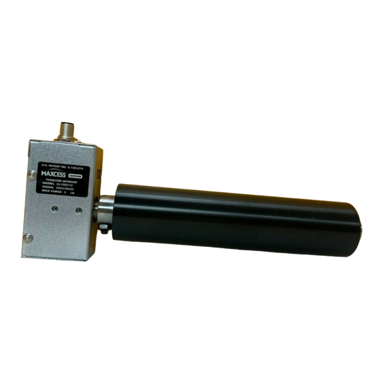
Models: CL1-5, CL1-15, CL1-50, CL2-50, CL2-150, CL2-500
(NOTE: DO NOT HAMMER ON CL LOAD CELLS OR TAMPER WITH THE INTERNAL COMPONENTS)
All of the information herein is the exclusive proprietary property of Maxcess International, and is disclosed with the
understanding that it will be retained in confidence and will neither be duplicated nor copied in whole or in part nor
be used for any purpose other than for which disclosed.
Copyright 2007, all rights reserved.
Periodically there will be updates to this manual. The latest version is available at
1-800-MAGPOWR (624-7697).
Remove envelope containing 4 setscrews from bore and install into sensor as shown below.
INTRODUCTION
The CL load cells are designed to be mounted on the vertical face of a machine side frame and to incorporate the
customer's cantilever shaft and roll assembly. The CL load cell can be mounted on either the inside or outside of
the machine side frame as shown in Figure 1.
MOUNTING
Select a clean flat surface where the wrap angle of the web does not change. Locate the centerline of the CL load
cell mounting holes, so that it bisects the wrap angle of the web. Fasten with two capscrews making sure the
capscrew penetration does not exceed dimension "N" shown on the outline dimension drawing. The force direction
arrow should also bisect the wrap angle of the web and point in the same direction as the resultant tension force as
shown in Figure 2.
NOTE: If the orientation of the load cell requires the force direction arrow to be pointed opposite the resultant
tension force direction, then the black (s-) and white (s+) sensor leads to the MAGPOWR control terminal block
must be reversed. (Figure 3)
SHAFT AND ROLL ASSEMBLY (SUPPLIED BY CUSTOMER)
Insert the customer's shaft and roll assembly into the CL load cell as shown below. Make sure that neither the
shaft nor the roll will interfere with the CL load cell housing or the machine side frame (for outside frame mountings
as shown below, the clearance hole in the machine side frame should be a minimum of .69 inch (17.5 mm)
diameter for CL1 models and a minimum of 1.06 inch (26.9 mm) diameter for CL2 models). Tighten all four
setscrews securely against the shaft. Connect the CL load cell to the control with shielded cable.
850A192-1
06/07 Rev. F
222 W. Memorial Road, Oklahoma City, OK 73114-2317
Phone: 1-800-624-7697 ⏐ Fax: 405-755-8425
www.magpowr.com ⏐ E-mail: magpowr@magpowr.com
INSTRUCTION MANUAL
CL CANTILEVER LOAD CELLS
Figure 1
www.magpowr.com
or by calling
Advertisement

Related Manuals for Maxcess Magpowr CL1-5


Summary of Contents for Maxcess Magpowr CL1-5
- Page 1 (NOTE: DO NOT HAMMER ON CL LOAD CELLS OR TAMPER WITH THE INTERNAL COMPONENTS) All of the information herein is the exclusive proprietary property of Maxcess International, and is disclosed with the understanding that it will be retained in confidence and will neither be duplicated nor copied in whole or in part nor be used for any purpose other than for which disclosed.
- Page 2 Figure 3 Wiring Diagram SPECIFICATIONS Figure 2 Gage resistance 350 ohms Excitation voltage 10 vdc nominal Output Signal 21 mvdc nominal per sensor at full load rating Operating Temperature -30°C to 95°C Combined Non-Linearity & Hysteresis 0.5% of full scale maximum (1.5% for CL2-500) Repeatability 0.2% of full scale maximum Deflection at full load...
Need help?
Do you have a question about the Magpowr CL1-5 and is the answer not in the manual?
Questions and answers