Table of Contents
Advertisement
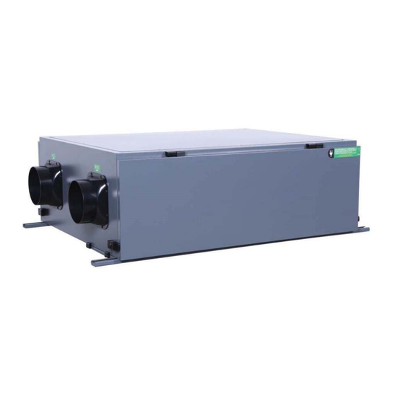
DanVex's
DD, DD-F, DD-FS, DD-FSR Series
DUCTED DEHUMIDIFIER
User's Manual
KEEP THESE INSTRUCTIONS FOR FUTURE REFERENCE
Thank you for choosing our dehumidifier. This owner's manual will provide you with
valuable information necessary for the proper care and maintenance of your new
dehumidifier. Please take a few moments to read the instructions thoroughly and
familiarize with all the operational aspects of this dehumidifier. This unit removes
excessive moisture from the air to create a more comfortable environment.
Page 1 of 39
Advertisement
Table of Contents

Related Manuals for DanVex DD Series


Summary of Contents for DanVex DD Series
- Page 1 DanVex’s DD, DD-F, DD-FS, DD-FSR Series DUCTED DEHUMIDIFIER User’s Manual KEEP THESE INSTRUCTIONS FOR FUTURE REFERENCE Thank you for choosing our dehumidifier. This owner’s manual will provide you with valuable information necessary for the proper care and maintenance of your new dehumidifier.
-
Page 2: Table Of Contents
3.11 Electrical connection ........................14 3.12 Sensitive elements connection ......................14 3.13 Wiring Diagram: DanVex DD Wiring diagrams the dehumidifier pasted on the body, and are available in the appendix of this manual........................14 3.14 Wiring Diagram: DanVex DD-F Wiring diagrams the dehumidifier pasted on the body, and are available in the appendix of this manual. - Page 3 4.1 Button Controller Module ........................17 4.3 Safety Cautions ..........................23 5 MAINTENANCES ....................24 5.1 Maintenance introduction ......................... 24 5.2 Filter ..............................24 5.3 Fan Motor ............................24 5.4.1 Maintenance during start of usage season ................25 5.4.2 Maintenance during end of usage season ................25 5.4.3 Maintenance of key components ...................
-
Page 4: Foreword
Foreword Purpose This manual provides all the information about this precise dehumidifier, including the structure, installation, principle, work process and the detailed operating instruction is provided. Content Dehumidifying control system, operating ways, maintain, and regular failure and failure elimination Rights Reserved We reserve the rights of updating/explaining all contents of manual involved. -
Page 5: Safety Introduction
1. SAFETY INTRODUCTION 1.1 Safety This series of dehumidifier is in conformance with all provisions of European security requirements and standards, the safety of worker and equipment are taken into care while in design and manufacture process. In each section of the manual, there are safety information and explicitly pointed out operation that may causes danger. -
Page 6: Introductions Of Device
2. INTRODUCTIONS OF DEVICE 2.1 Standards The design meets IEC protection class IP 45 requirements. 2.2 Structure 2.2.1 Housing and body Adopts steel frame structure, compact, strong, robust, and the defrosting technology effectively preventing the "frozen" issue; Easy to open / access panel for replacing filter Water tray equipped ensures that all condensate water drain out, preventing water stagnation. -
Page 7: Protection Devices
Fans operation mode: The fan will run and stop according to the RH setpoint. High temperature protection: Prevent the compressor running continuously at high temperatures; Low pressure protection: Prevents the dehumidifier running without refrigerant to avoid compressor from being overload. 2.2.7 Product Diagram DD Series Page 7 of 39... - Page 8 DD - F Series Page 8 of 39...
-
Page 9: Installations
3. INSTALLATIONS 3.1 Brief introduction Ceiling Mounted dehumidifier can be installed in many places, depending on the requirements of owners. It can also integrate with current ventilation system via duct system. This chapter records info about preparation work, and installation work and etc. Please serve it as a guide before installation. -
Page 10: Ground/Base
process air’s dew point. Please place the device near to power source. NOTE: Please provide enough space around the dehumidifier for troubleshooting and maintenance service purpose. 3.6 Ground/Base Dehumidifier must be installed horizontally with well-balanced level. Please use horizontal ruler to measure the level during installation. -
Page 11: Ducting Connection Diagram (Example)
3.8 Ducting Connection Diagram (example) Page 11 of 39... -
Page 12: Service Access Space Allocation
3.9 Service Access Space Allocation Please allocate the space require as per the table for access to service the unit. Service Area Void Area / No Blockage Model DD -26 / 26F 400mm 490mm 100mm 100mm DD -36 / 36F 500mm 600mm 100mm... -
Page 13: Drain Pipe Connection
3.10 Drain pipe connection Drain pipe is a transparent hose, please connect it as per the drawing as below: It is strongly advised to install a U-Trap with PVC pipe or any other pipe that are suitable. This would help to allow the condensate water flow out smoothly. Page 13 of 39... -
Page 14: Electrical Connection
External control system must be compatible with the low voltage control circuit of dehumidification equipment. 3.13 Wiring Diagram: DanVex DD Wiring diagrams the dehumidifier pasted on the body, and are available in the appendix of this manual. 3.14 Wiring Diagram: DanVex DD-F Wiring diagrams the dehumidifier pasted on the body, and are available in the appendix of this manual. -
Page 15: Machine Picture Diagram
3.15 Machine Picture Diagram 3 Phase Wiring Protector Heat Compressor EC Fan Filters Terminal & Exchanger Contactor Green Connector & Controller To connect between Machine and Controller Page 15 of 39... - Page 16 Supply Air Outlet DD Series DD-F Series Return Air Inlet - DD Series Fresh Air Damper and Return Air Inlet - For DD-F Series Page 16 of 39 of 39...
-
Page 17: Operations
4. OPERATIONS 4.1 Button Controller Module This unit of controller is built-in with Honeywell temperature and humidity sensor to monitor indoor temperature and humidity in real time. The controller comes with physical buttons for functional and easy operation. The controller provides functions to control the machine On/Off, Humidity Setting, Fresh Air Valve On/Off, Adjust Fan Speed (depending on models and available fan settings) and many other functions. - Page 18 Basic Functions: RS485 communication connection (2-wires) is available. It uses MODBUS protocol to communicate. Temperature and Humidity display and setting. 3. Wireless communication function (WIFI). Press for few seconds, WIFI icon will appear and flashing, at the same time the IMEI number will appear, after a minute of no activity it will auto log off.
- Page 19 9. Auto / Manual Mode. Press to switch between Auto or Manual mode. Auto mode: during this mode, it will automatically turn on and off the dehumidifying function based on setpoint value. Manual mode: Press and hold for few second, it will start the dehumidifying function. Press and hold for few second again, it will turn off the dehumidifying function.
- Page 20 first replacement timer is 1000 hours, follow by second replacement is 4000 hours, third replacement is 6000 hours and the next following will be 6000 hours interval. Display Interface: 1. The controller will resume to the same state on the next startup regardless due to power failure or manual shutdown of power.
- Page 21 Operation Setting Menu: 1. Press and hold the setting button to enter the operation setting menu. Quick press of setting button will act as ‘confirm’ function to confirm on the parameter being set and will enter the next parameter setting. Press and hold the setting button to confirm the current parameter setting and exit.
- Page 22 MODBUS protocol and RS485 address Hardware: RS485 Protocol: MODBUS RTU Baud rate 9600 (EEPROM can be set), 8-bit data, 1-bit stop, no check bits. Low priority. Read data Slave Function Format: Start Address Register Number CRC16 Address Code 1 byte 1 byte 2 bytes 2 bytes...
-
Page 23: Safety Cautions
Setting (Commands of the master controller to the dehumidifier controller): 0x01 Machine Condition 1: Indicate in operation 2: Start 0: Off 0x02 Fan Speed 1-3 3 level fan speed Note: The remote Read Current temperature and 0x03 Humidity Level (%) humidity will not work until it is turned on. -
Page 24: Maintenances
5 MAINTENANCES 5.1 Maintenance introduction The dehumidifier system can run for a long time and requires very little maintenance. The maintenance of the dehumidifier is beneficial to the long-term operation of the unit. The frequency of maintenance depends on the operating conditions of the unit, and the quality of the installation environment. -
Page 25: Maintenance During Start Of Usage Season
• According to the replacement parts, it is recommended to replace the primary filter and the intermediate filter every 6-8 months, and replace the high efficiency filter every 12 months. • It is recommended to replace the heat exchange core (DanVex DD-FSR) every 24 months, which can be replaced by rotating the fixing piece. - Page 26 Component 3 months 6 months 9 months It is recommended Clean primary Replace G4 primary G4 primary filter to replace the G4 filtration filter filter Clean F7 secondary Clean F7 secondary Replace F7 secondary F7 Secondary filter filter filter filter Check the compressor Check whether the wiring and make sure...
-
Page 27: Inspection And Maintenance Procedures
5.5 Inspection and maintenance procedures 1. Outer inspection at least once a month Ensure that the exhaust and fresh air enclosures are not blocked or blocked by leaves, grass or snow. During winter, it is particularly important not to allow snow to block the tube cover or filter frost (anti-bird net). - Page 28 When installing the machine, it must be ensured that the connecting pipe is securely connected before starting the compressor. If the compressor is started before the connection of the connecting pipe is completed and the shut-off valve is opened, air will mix in causing the system pressure to rise, and a compressor burst accident may cause injury.
-
Page 29: Troubleshooting
6. Troubleshooting In the following cases, please contact your local DanVex’s representative. Harsh sound during operation. Air switches or leakage protection switches are often turned off. Accidentally poured impurities or water into the machine or controller. Pungent smell during operation. - Page 30 Failure symptoms Troubleshooting steps recommended No dehumidification. Machine is not in 1. The device is not plugged in, or there is no power operation. The fan and compressor are supply to the power outlet not running, and the controller is not 2.
- Page 31 The device is able to drain some water 1. Air temperature and / or humidity drops but does not reach the expected 2. Humidity Level on the controller require calibration performance. 3. The device has entered the defrost cycle working state 4.
-
Page 32: Appendix
The equipment should be operated with proper usage and regular maintenance, as evident with the service records of the authorized personnel. This unit must not be serviced by any personnel NOT authorized by DanVex Oy. This warranty covers manufacturing defects and does NOT cover parts subjected to conditions of use outside of specifications in operation manual and those exposed to normal wear and tear. -
Page 33: Wiring Diagram
7.2 Wiring Diagram Page 33 of 39... - Page 34 Page 34 of 39...
- Page 35 Page 35 of 39...
- Page 36 Page 36 of 39...
- Page 37 Page 37 of 39...
- Page 38 Page 38 of 39...
- Page 39 Page 39 of 39...
Need help?
Do you have a question about the DD Series and is the answer not in the manual?
Questions and answers