Table of Contents
Advertisement
Quick Links
Advertisement
Table of Contents

Subscribe to Our Youtube Channel
Related Manuals for CKD PNA Series


Summary of Contents for CKD PNA Series
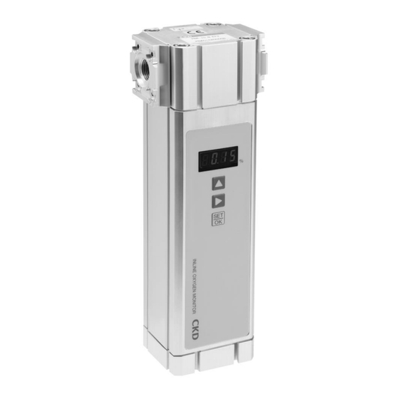
- Page 1 Inline Oxygen Monitor PNA Series INSTRUCTION MANUAL INSTRUCTION MANUAL SM-A10371-A/3 SM-358642 • Read this Instruction Manual before using the product. • Read the safety notes carefully. • Keep this Instruction Manual in a safe and convenient place for future reference.
-
Page 2: Preface
PREFACE PREFACE Thank you for purchasing CKD's inline oxygen monitor. This Instruction Manual contains basic matters such as installation and usage instructions in order to ensure optimal performance of the product. Please read this Instruction Manual thoroughly and use the product properly. -
Page 3: Safety Information
SM-A10371-A/3 SAFETY INFORMATION SAFETY INFORMATION When designing and manufacturing any device incorporating the product, the manufacturer has an obligation to ensure that the device is safe. To that end, make sure that the safety of the machine mechanism of the device, the pneumatic or water control circuit, and the electric system that controls such mechanism is ensured. -
Page 4: Precautions On Product Use
• For applications where life or properties may be adversely affected and special safety measures are required. (Exception is made if the customer consults with CKD prior to use and understands the specifications of the product. However, even in that case, safety measures must be taken to avoid danger in case of a possible failure.) -
Page 5: Table Of Contents
SM-A10371-A/3 CONTENTS CONTENTS PREFACE ........................... i SAFETY INFORMATION ....................ii Precautions on Product Use ..................iii CONTENTS ........................iv 1. PRODUCT OVERVIEW ....................1 1.1 Description of operation ................... 1 1.2 Part name ........................ 2 1.3 Model Number Indication ..................3 1.4 Specifications and characteristics ................ -
Page 6: Product Overview
SM-A10371-A/3 1. PRODUCT OVERVIEW 1. PRODUCT OVERVIEW 1.1 Description of operation ◼ Overview This device has a highly reliable O2 detection element using stabilized zirconia solid electrolyte and can measure the oxygen concentration upon power-up, without requiring any reference gas. It has a switch output port and an analogue output port and can be easily connected to any external device or recorder. -
Page 7: Part Name
SM-A10371-A/3 1. PRODUCT OVERVIEW 1.2 Part name LED display UP key Right key OK key AC power adaptor DC cable connector connector M3 female screw for Grounding terminal connection April 7, 2020... -
Page 8: Model Number Indication
SM-A10371-A/3 1. PRODUCT OVERVIEW 1.3 Model Number Indication *Connector cable is not included. Refer to see the page 10 for details. April 7, 2020... -
Page 9: Specifications And Characteristics
Note 4 About 5 minutes after power-up Note 1: Contact CKD when 500 L/min (ANR) is exceeded. Note 2: Value measured in dry gas consisting of oxygen and nitrogen. Note 3: The response times are for flow rates of 5 L/min (ANR) or more. -
Page 10: Installation
2.1 Environment WARNING Before using the product under conditions not specified for the product or for special applications, make sure to consult CKD about its specifications. CAUTION Observe the following rules about installation environment. Do not use the product at a place exposed to direct sunlight or rainwater. -
Page 11: Mounting
SM-A10371-A/3 2. INSTALLATION 2.3 Mounting WARNING Avoid applying any piping load or torque to pipes. Avoid fixing a pipe in the way. because such a fixation method puts the pipe under an excessive force, leading to breaking. CAUTION Tighten the screws with the appropriate tightening torque. If assembly or tightening is not properly done, it may result in air leakage, product falling off, screw breakage, or deformation of DIN rails. - Page 12 SM-A10371-A/3 2. INSTALLATION ◼ Module connection with pneumatic components Module connection combines the product into one unit with pneumatic components (C2000, C3000, C4000 Series). Following parts are required for combining into one unit. Part name Model number Joiner set C4000-J400-W B310-W (for C2000, C3000 Series) T-type bracket set B410-W (for C4000 Series)
-
Page 13: Piping
SM-A10371-A/3 2. INSTALLATION 2.4 Piping CAUTION Tighten the pipes with appropriate tightening torque. Observe the appropriate tightening torque to prevent air leakage and damage to the threads. To prevent damage to the screw threads, first use your hands to lightly tighten the screw and then use a tool to tighten the pipe further. -
Page 14: Piping Direction
SM-A10371-A/3 2. INSTALLATION 2.4.4 Piping direction Fluid can flow in any direction. 2.5 Wiring DANGER Do not put the device under a voltage out of the supply voltage range. A voltage exceeding the specified supply voltage range may lead to bursting, electric shock or fire. WARNING When wiring, be sure to check the colors of the connector pins and cable conductors. -
Page 15: Ac Adaptor
SM-A10371-A/3 2. INSTALLATION 2.5.1 AC adaptor If the device is fed from AC power supply, use an AC adaptor. PNA-A 、PNA-AG (With conversion plug B、C、O、BF) Model Input voltage AC90V to AC264V Output voltage 24.0 V DC ±1.2 V Phoenix Contact SACC-M8FS-3CON-M-SH Connector shape (3-pin, socket type, M8 size) Full view of AC adaptor... -
Page 16: Connection
SM-A10371-A/3 2. INSTALLATION 2.5.3 Connection Remove the water proof caps from “AC adaptor connector” and “DC cable connector” on the bottom of the product. To feed the product from AC adaptor, connect a dedicated AC adaptor to “AC adaptor connector”. Connect a DC cable or a cable prepared by yourself to “DC cable connector”. -
Page 17: Example Of Wiring
SM-A10371-A/3 2. INSTALLATION 2.5.5 Example of wiring When using the DC cable, wire according to the following example. Oxygen Monitor (White)Power supply + Power supply circuit 24V DC (Brown)Power supply - (Green)Analogue output + Receiving 4 – 20mA instrument Output circuit (Yellow)Analogue output - (Gray)Switch output 24V DC... -
Page 18: Usage
SM-A10371-A/3 3. USAGE 3. USAGE WARNING Stop the device before changing any set value. The control system may function in an unintended way. Do not disassemble or modify the product. Doing so may lead to a failure. 3.1 Action up to start of measurement (warm-up) The product starts operation upon power-up. -
Page 19: Operation Method Before Start Of Measurement
SM-A10371-A/3 3. USAGE 3.2 Operation method before start of measurement Name of Purpose Action keys Switch the display OK key Short press between oxygen When decimal point is lit: Oxygen concentration concentration and When decimal point is blinking: Nitrogen concentration (100-oxygen concentration) nitrogen concentration Change upper and lower OK key... - Page 20 SM-A10371-A/3 3. USAGE Table 1. Operation flow diagram Mode Operation flow and display Remarks Normal operation mode The device displays the measured oxygen OK key concentration and gives switch outputs according to the (Long set upper and lower limit values. press) ...
-
Page 21: Action After Start Of Measurement
SM-A10371-A/3 3. USAGE 3.3 Action after start of measurement 4-20 mA analogue output In normal conditions, the transmission signal corresponding to the measured oxygen concentration is outputted. Minimum output 4 mA (0.00%O value Maximum 20 mA (25.00%O output value Resolution 0.064 mA (0.1%O Load range 0 to 400 Ω... -
Page 22: Switch Output Action
SM-A10371-A/3 3. USAGE 3.4 Switch output action Relationship between upper and lower limits and switch output action Lower limit Upper limit Measured value Switch non-output status range Lower limit Switch output status range Switch non-output Switch output Upper limit status range status range Switch output Switch output action status [... -
Page 23: Maintenance And Inspection
Keep it in a place free from strong shocks. Turn off the power in case of any abnormality In case of abnormal smell, abnormal noise, smoke or high temperature, turn off the power and contact your nearest sales office or dealer of CKD. April 7, 2020... -
Page 24: Troubleshooting
Switch output is not The lower limit or upper limit is set to a wrong Check the set values. made. value. If you have any other questions or concerns, contact your nearest CKD sales office or dealer. April 7, 2020... -
Page 25: Warranty Provision
If the product specified herein fails for reasons attributable to CKD within the warranty period specified below, CKD will promptly provide a replacement for the faulty product or a part thereof or repair the faulty product at one of CKD’s facilities free of charge. -
Page 26: Warranty Period
SM-A10371-A/3 6. WARRANTY PROVISION ◼ Confirmation of product compatibility It is the responsibility of the customer to confirm compatibility of the product with any system, machinery, or device used by the customer. 6.2 Warranty Period The product is warranted for one (1) year from the date of delivery to the location specified by the customer.
Need help?
Do you have a question about the PNA Series and is the answer not in the manual?
Questions and answers