Table of Contents
Advertisement
Quick Links
Advertisement
Table of Contents

Related Manuals for CKD NSU Series


Summary of Contents for CKD NSU Series
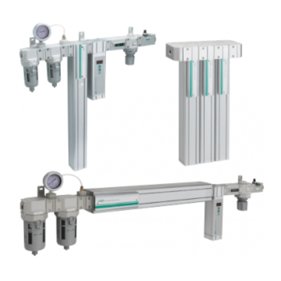
- Page 1 SM-A09607-A INSTRUCTION MANUAL NITROGEN GAS EXTRACTION UNIT SYSTEM TYPE NSU series Read this Instruction Manual before ● using the product. Read the safety notes carefully. ● Keep this Instruction Manual in a ● safe and convenient place for future reference.
- Page 3 It is not intended for use outdoors (except for products with outdoor specifications) or for use under the following conditions or environments. (Note that this product can be used when CKD is consulted prior to its usage and the customer consents to CKD product specifications. The customer should provide safety measures to avoid danger in the event of problems.)
- Page 4 Warranty period of this product is one year after purchase. 2. Scope of warranty If any malfunction or damage occurs on the CKD’s own responsibility within above warranty period, we will repair the product immediately free of charge. However, the following are excluded from warranty.
-
Page 5: Table Of Contents
Table of Contents 1. INTRODUCTION ·································································· 4 2. PRODUCTS 2-1 Specifications ································································ 5,6,7,8 2-2 Selection guide ································································· 9,10 2-3 Dimensions ··········································· 11,12,13,14,15,16,17,18 2-4 Needle valve flow characteristics ············································· 19 3. CAUTION ··········································· 20 Chemical Resistance of Plastic Bowls ············································································ 21,22 Others 4. -
Page 6: Introduction
1. INTRODUCTION Thank you for purchasing CKD’s "Nitrogen gas extraction unit, system type". This manual explains basic points of installation, operation, etc. to have our Nitrogen gas extraction unit, system type perform at their best. Please read this Instruction Manual thoroughly and use the product properly. -
Page 7: Products
*6. When the membrane unit size "L" is selected and the outlet nitrogen gas with a concentration of 90% is used, inlet air temperature should be 40°C or less. Contact CKD if you want to use the product when inlet air temperature is above 40°C. - Page 8 Components Standard ( Port size Rc 3/8 ) Unit model No. NSU-3S □ NSU-3L □ NSU-4S □ NSU-4F □ NSU-4L □ NSU-4G □ NSU-4H □ F3000-10-W-F F4000-10-W-F Air filter M3000-10-W-F1 M4000-10-W-F1 Oil mist filter Differential GA400-8-P02 pressure gauge Membrane unit NS-4S110A NS-4L110A NS-4L110A...
- Page 9 Standard ( Port size G 3/8 ) Unit model No. NSU-3S □ NSU-3L □ NSU-4S □ NSU-4F □ NSU-4L □ NSU-4G □ NSU-4H □ F3000-10G-W-F F4000-10G-W-F Air filter M3000-10G-W-F1 M4000-10G-W-F1 Oil mist filter Differential GA400-8-PB02 pressure gauge Membrane unit NS-4S110B NS-4L110B NS-4L110B NS-3S110B...
- Page 10 Standard ( Port size NPT 3/8 ) Unit model No. NSU-3S □ NSU-3L □ NSU-4S □ NSU-4F □ NSU-4L □ NSU-4G □ NSU-4H □ F3000-10N-W-F F4000-10N-W-F Air filter M3000-10N-W-F1 M4000-10N-W-F1 Oil mist filter Differential GA400-8-PS02 pressure gauge Membrane unit NS-4S110C NS-4L110C NS-4L110C NS-3S110C...
-
Page 11: Selection Guide
2-2. Selection guide Model selection method 〈 〉 As temperature and inlet air pressure affect outlet nitrogen gas flow rate, correction is required if they differ from the rated values listed in the specifications. STEP1 Confirm the use conditions and the rated values in the specifications. Outlet nitrogen gas flow rate [L/min(ANR)] Outlet nitrogen gas pressure [MPa] Inlet air pressure [MPa]... - Page 12 STEP7 Confirm the compensation coefficient for inlet air flow rate affected by inlet air temperature. (3) Temperature – Air flow rate correction coefficient Outlet nitrogen gas concentration Temperature (°C) 99.9% 0.73 0.68 0.75 0.69 0.76 0.76 0.81 0.77 0.82 1.21 1.17 1.11 1.13...
-
Page 13: Dimensions
2-3. Dimensions 1-station type, no inline oxygen monitor and flow sensor 〈 SM-A09607-A 〉... - Page 14 1-station type, with inline oxygen monitor, no flow sensor 〈 SM-A09607-A 〉...
- Page 15 1-station type, no inline oxygen monitor, with flow sensor 〈 SM-A09607-A 〉...
- Page 16 1-station type, with inline oxygen monitor and flow sensor 〈 SM-A09607-A 〉...
- Page 17 2-station type, no inline oxygen monitor and flow sensor 〈 SM-A09607-A 〉...
- Page 18 2-station type, with inline oxygen monitor, no flow sensor 〈 SM-A09607-A 〉...
- Page 19 2-station type, no inline oxygen monitor, with flow sensor 〈 SM-A09607-A 〉...
- Page 20 2-station type, with inline oxygen monitor and flow sensor 〈 SM-A09607-A 〉...
-
Page 21: Needle Valve Flow Characteristics
2-4. Needle valve flow characteristics * The flow rate characteristics graph gives reference values and does not guarantee the values. Dial value (needle position) Dial value (needle position) Dial value (needle position) Dial value (needle position) Dial value (needle position) 〈... -
Page 22: Caution
3. CAUTION 3-1. Chemical Resistance of Plastic Bowls Prevent installation of bowls within the following chemical periphery because the bowls are made of polycarbonate. Types of Categories of Main products of chemicals General applications chemicals chemicals Hydrochloric acid, sulfuric acid, Acid washing of metals, acidic Acids fluorine, phosphoric acid, chromic... -
Page 23: Others
3-2. Others 1. Working environment 1) Avoid installing this product where it will be subject to direct sunlight or rain. 2) Avoid use in environments where ozone is generated. 3) Avoid using this product where vibration and impact are present. 4) Avoid use in environments with moist air with a relative humidity of 50% or higher. - Page 24 3. Caution of needle valve with adjusting dial 1) To adjust the flow rate, turn the dial to the right to open or the left to close. 2) After adjustment, lock the dial with the sliding lock lever. 3) The flow rate control range is from “1” to “12” or “13” on the dial rotation display. Do not set the flow rate outside this range.
-
Page 25: Operation
4 .OPERATION 4-1. Pressure setting 1) Pull down knob and rotate it after confirming not locked. (Refer to Fig.1) 2) Rotating H-direction (Clockwise) increases pressure, while L- direction (Counter-Clockwise) for decrease. (Refer to Fig.2) 3) Knob cannot be rotated when they are pushed to be locked. (Refer to Fig.2) NOTE: Use in setting pressure range. -
Page 26: Piping
5 .INSTALLATION 5-1. Piping 1) Ensure air flow coincides with the directional arrows on cover plate. 2) Flush air into the pipe to blow out foreign substances and chips before piping. 3) Refrain applying sealant or sealing tape approx. Two pitches of thread off the tip of pipe to avoid residual substances from falling into piping system. - Page 27 5-2. Installation ■ When the mounting direction "No sign: Vertical mounting" is selected. 1) Installation is made with mounting hole of T type bracket. Refer to outline drawing. 2) Install so that drain discharge port faces downward. 3) Install as close to the pneumatic equipment as possible. 4) Allow a minimum of 20 mm above the top and 30 mm below the unit for maintenance purpose.
- Page 28 ■ When the mounting direction "T: Horizontal mounting" is selected. 1) Installation is made with mounting hole of T type bracket. Refer to outline drawing. 2) Install so that drain discharge port faces downward. 3) Install as close to the pneumatic equipment as possible. 4) Allow a minimum of 20 mm above the top and 60 mm under the filter for maintenance purpose.
-
Page 29: Operation Start/Stop And Inspection
6. OPERATION START/STOP AND INSPECTION 6-1. Operation start/stop 〈 Operation start 〉 1) After the regulator and needle valve is fully closed, gradually open the primary side valve. 2) Set the secondary side of the regulator to 0.7 MPa or less, gradually open the needle valve and adjust to a predetermined outlet nitrogen gas flow rate and oxygen concentration. -
Page 30: Maintenance
7 .MAINTENANCE 7-1. Periodical inspection 1) Perform periodical check if drain level does not exceed max drain level. 2) Pressure differential 0.07 MPa shows life time for oil mist filter, then element to be replaced by new one. 3) Use household detergent to wash the plastic bowl. 4) Do not use anything other than household detergents 7-2. -
Page 31: Element Replacement
7-3. Element replacement Air filter Remove buffle by which element is fixed, after removing bowl. Use hex key wrench as buffle has hex. hole at lower part. Buffle, element and louver are removed at the same time. Follow the reverse steps when assembled. (Hex key wrench to be used…F3000: 10 mm, F4000: 14 mm) (14) ... -
Page 32: Membrane Module Replacement
7-4. Membrane module replacement ■ When the mounting direction "No sign: Vertical mounting" is selected. 1) Slide silencer downward by loosening two set screws at silencer portion with hex key wrench. (2.5 mm) (In case of option E, shift supporter up and down, and remove exhaust adapter.) 2) Remove membrane module downward by loosening four hex socket bolts. (Upper face) with hex key wrench. - Page 33 ■ When the mounting direction "T: Horizontal mounting" is selected. 1) Slide silencer rightward by loosening two set screws at silencer portion with hex key wrench. (2.5 mm) (In case of option "D, F, E, H ", shift supporter left and right, and remove exhaust adapter.) 2) Remove membrane module by loosening each four hex socket bolts from the left and right covers with hex key wrench (6 mm).
-
Page 34: Model Coding
8. MODEL CODING 〈 SM-A09607-A 〉... - Page 35 〈 SM-A09607-A 〉...
- Page 36 Phone: +1-847-648-4400 Fax: +1-847-565-4923 Phone: +66-(0)2-267-6300 Fax: +66-(0)2-267-6304/6305 Mexico Vietnam CKD Mexico, S. de R.L. de C.V. CKD Vietnam Engineering Co., Ltd. Cerrada la Noria No. 200 Int. A-01, Querétaro Park II, 18th Floor, CMC Tower, Duy Tan Street, Cau Giay District, Parque Industrial Querétaro, Santa Rosa Jáuregui,...
Need help?
Do you have a question about the NSU Series and is the answer not in the manual?
Questions and answers