Table of Contents
Advertisement
Quick Links
Advertisement
Table of Contents

Related Manuals for CKD HMF Series


Summary of Contents for CKD HMF Series
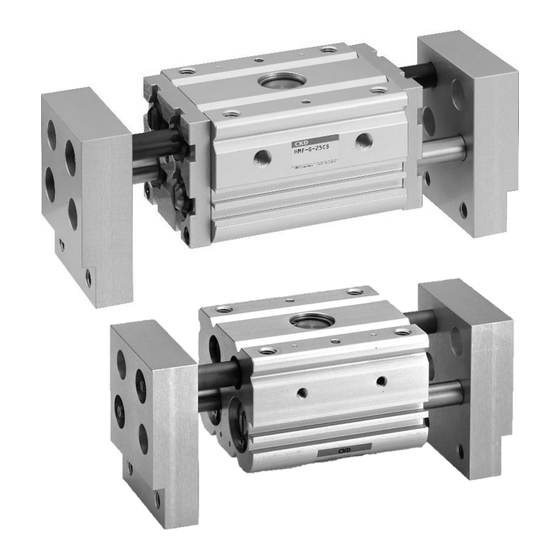
- Page 1 Compact Wide Parallel Hand HMF Series INSTRUCTION MANUAL SM-A26328-A/2 • Read this Instruction Manual before using the product. • Read the safety notes carefully. • Keep this Instruction Manual in a safe and convenient place for future reference.
-
Page 2: Preface
• Since there are a wide variety of customer applications, it is impossible for CKD to be aware of all of them. Depending on the application or usage, the product may not be able to exercise its full performance or an accident may occur due to fluid, piping, or other conditions. -
Page 3: Safety Information
SM-A26328-A/2 SAFETY INFORMATION SAFETY INFORMATION When designing and manufacturing any device incorporating the product, the manufacturer has an obligation to ensure that the device is safe. To that end, make sure that the safety of the machine mechanism of the device, the fluid control circuit, and the electric system that controls such mechanism is ensured. -
Page 4: Precautions On Product Use
• For applications where life or properties may be adversely affected and special safety measures are required. (Exception is made if the customer consults with CKD prior to use and understands the specifications of the product. However, even in that case, safety measures must be taken to avoid danger in case of a possible failure.) -
Page 5: Precautions On Product Disposal
SM-A26328-A/2 SAFETY INFORMATION Precautions on Product Disposal CAUTION When disposing of the product, comply with laws pertaining to disposal and cleaning of wastes and have an industrial waste disposal company dispose of the product. 2020-04-29... -
Page 6: Table Of Contents
Precautions on Product Disposal .................. iv CONTENTS ........................v PRODUCT OVERVIEW ..................... 1 Model Number Indication ..................1 1.1.1 HMF Series ..................... 1 1.1.2 HMF-G Series ....................2 1.1.3 Switch model number ..................2 Specifications ...................... 3 1.2.1 Product specifications ..................3 1.2.2 Switch specifications .................. -
Page 7: Product Overview
SM-A26328-A/2 1. PRODUCT OVERVIEW 1. PRODUCT OVERVIEW 1.1 Model Number Indication 1.1.1 HMF Series ◼ Example of model number indication Note1: 12CS is not available for long stroke “L1”, “L2”. 2020-04-29... -
Page 8: Hmf-G Series
SM-A26328-A/2 1. PRODUCT OVERVIEW 1.1.2 HMF-G Series ◼ Example of model number indication 1.1.3 Switch model number 2020-04-29... -
Page 9: Specifications
SM-A26328-A/2 1. PRODUCT OVERVIEW 1.2 Specifications 1.2.1 Product specifications HMF-16CS HMF-20CS HMF-25CS HMF-32CS HMF-40CS HMF- Descriptions 12CS Std. Std. Std. Std. Std. φ12×2 φ16×2 φ20×2 φ25×2 φ32×2 φ40×2 Bore size Compressed air Working fluid Max. working pressure Min. working pressure Ambient °C 5 to 60... -
Page 10: Switch Specifications
SM-A26328-A/2 1. PRODUCT OVERVIEW 1.2.2 Switch specifications Proximity 2-wire type Proximity 3-wire type Descriptions T2H/V T3H/V Only for programmable controller For programmable controller, relay Applications Output method - - 10 VDC to 28 VDC Power supply voltage 10 VDC to 30 VDC 30 VDC or less Load voltage 100 mA or less... -
Page 11: Installation
SM-A26328-A/2 2. INSTALLATION 2. INSTALLATION 2.1 Environment CAUTION When using the product in a cutting, casting, or welding plant, install a cover to prevent foreign matters such as cutting fluid, chips, powder, and dust from entering. Do not use the equipment in the following environments. •... -
Page 12: Mounting
SM-A26328-A/2 2. INSTALLATION 2.3 Mounting 2.3.1 Mounting the body The body can be mounted from three directions. Select the mounting direction appropriate for the application.Do not put any dents and scratches on the body mounting surface or the finger that may affect their flatness and perpendicularity. - Page 13 SM-A26328-A/2 2. INSTALLATION ◼ Allowable load Gripping power represents the force holding the workpiece, as shown in the figure below. Performance data indicates the gripping power at hand finger length ℓ at a supply pressure of 0.3 to 0.7 MPa. Finger Workpiece To find the gripping power from performance data, if the distance from the attachment to the workpiece...
-
Page 14: Finger
SM-A26328-A/2 2. INSTALLATION 2.3.2 Finger ◼ Rigidity of the attachment If the attachment is not rigid enough, sagging can result and cause the finger to twist or adversely affect operation. ◼ Mounting the attachment The effect on the hand body must be taken into consideration when mounting the attachment to the finger. - Page 15 SM-A26328-A/2 2. INSTALLATION • When gripping long or large workpieces, stable gripping requires a grip on the center of gravity. Stability is a must when using larger or multiple workpieces as well. • Select a model that has sufficient opening / closing width for the workpiece size. •...
-
Page 16: Mounting The Switch
SM-A26328-A/2 2. INSTALLATION 2.3.3 Mounting the switch ◼ Mounting position For the switch to function at an intermediate position of the stroke, secure the piston at the position where the switch needs to function and then slide the switch on the piston back and forth to find the positions where the switch turns on when slid forward and when slid backward. - Page 17 SM-A26328-A/2 2. INSTALLATION ◼ Changing the position of the switch Loosen the fastening screw (set screw). Move the switch body along the groove on the side of the body or the rail plate and then tighten the screw at the predetermined position. ◼...
-
Page 18: Piping
SM-A26328-A/2 2. INSTALLATION 2.4 Piping 2.4.1 Piping WARNING Insert the tube into the fitting until it firmly rests on the tube end and make sure that the tube does not come off before use. • Use pipes that are made of corrosion-resistant materials after the filter such as zinc-plated pipes, nylon tubes, and rubber tubes. - Page 19 SM-A26328-A/2 2. INSTALLATION ◼ Seal material Use a seal tape or a seal material to stop leakage from piping. Apply a seal tape or seal material to the screw threads leaving two or more threads at the pipe end uncovered or uncoated. If the pipe end is fully covered or coated, a shred of seal tape or residue of seal material may enter inside of the pipes or device and cause a failure.
-
Page 20: Wiring
SM-A26328-A/2 2. INSTALLATION 2.5 Wiring 2.5.1 Proximity switch ◼ Connection of lead wires Turn off the power to the device in the electric circuit to which the switch is to be connected and connect the lead wires according to their color. Not turning off the power may cause damage to the electric circuit of the switch load. - Page 21 SM-A26328-A/2 2. INSTALLATION ◼ Protection of the output circuit For the following cases, refer to the figures below and install a protection circuit: • When an inductive load (relay or solenoid valve) is connected and used: See Ex. 1 Use a surge absorption element since a surge voltage is generated when the switch is turned off. •...
- Page 22 SM-A26328-A/2 2. INSTALLATION ◼ Connection to the programmable controller The connection method depends on the type of the programmable controller. Connect as shown below. Programmable controller Programmable controller Blue Brown Blue Brown Switch Switch Input Input termi- termi- nals nals Blue Brown Blue...
-
Page 23: Usage
SM-A26328-A/2 3. USAGE 3. USAGE 3.1 Using the Hand CAUTION Do not apply excessive load to the finger when attaching, removing, or transferring the workpiece. Scratches and dents may occur on the rolling surface of the finger linear guide and possibly cause a malfunction. -
Page 24: Maintenance And Inspection
SM-A26328-A/2 4. MAINTENANCE AND INSPECTION 4. MAINTENANCE AND INSPECTION WARNING Do not disassemble the product. Do not touch electrical wiring connections (bare live parts) of actuators equipped with switches, and other such actuators. Do not touch live parts with bare hands. An electric shock may occur. -
Page 25: Periodic Inspection
SM-A26328-A/2 4. MAINTENANCE AND INSPECTION 4.1 Periodic Inspection In order to use the product under optimum conditions, perform a periodic inspection every six months or when the operation count reaches 5 hundred thousand times. 4.1.1 Inspection item • Actuation state •... -
Page 26: Internal Structure
SM-A26328-A/2 4. MAINTENANCE AND INSPECTION 4.1.4 Internal structure ◼ HMF Series HMF-12CS to 25CS (Standard) HMF-32CS,40CS(Standard) HMF-16CS to 40CS-L1,L2(Long stroke) Parts list Part name Material Remarks Washer Carbon steel 12CS and 16CS only Needle bearing sealant Resin + steel Bush... - Page 27 SM-A26328-A/2 4. MAINTENANCE AND INSPECTION ◼ HMF-G Series HMF-G(Standard) HMF-G(L1,L2) Parts list Part name Material Remarks Hexagon socket head bolt Steel alloy Flat washer Steel Washer Steel 16CS only Side cover Aluminum alloy Dust wiper Nitrile rubber, steel Needle bearing sealant Resin, steel Bush Sintering oil impregnated alloy...
-
Page 28: Troubleshooting
SM-A26328-A/2 5. TROUBLESHOOTING 5. TROUBLESHOOTING 5.1 Problems, Causes, and Solutions If the product does not operate properly, check the table below for a possible solution. 5.1.1 Finger (cylinder) Problem Cause Solution No pressure or insufficient pressure is applied. Secure sufficient pressure. No signal is input to directional control valve. -
Page 29: Switch
Ambient temperature is too high or too low. to 60°C. Magnetic field is nearby. Install a magnetic shield. External signal is faulty. Check the external circuit. If you have any other questions or concerns, contact your nearest CKD sales office or distributor. 2020-04-29... -
Page 30: Warranty Provisions
If the product specified herein fails for reasons attributable to CKD within the warranty period specified below, CKD will promptly provide a replacement for the faulty product or a part thereof or repair the faulty product at one of CKD’s facilities free of charge.
Need help?
Do you have a question about the HMF Series and is the answer not in the manual?
Questions and answers