ATEN US3344I - 4x4 USB 3.1 Gen 1 Industrial Hub Switch Quick Start Guide
- User manual (26 pages) ,
- User manual (31 pages) ,
- User manual (33 pages)
Advertisement
Package Contents
- 1 4x4 USB 3.1 Gen 1 Industrial Hub Switch
- 2 USB 3.1 Gen 1 Type-B to Type-A Cable 1.2M
- 2 USB 3.1 Gen 1 Type-B to Type-A Cable 1.8M
- 1 Remote Port Selector
- 1 Mounting Kit
- 1 Terminal Block Adapter Set (an RS-422/RS-485 and a DC terminal block adapter)
- 1 User Instructions
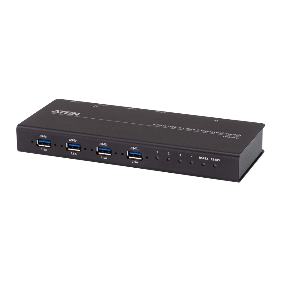
Hardware Review
Front view

- USB Type-A Peripheral Port
- Port Indicator LEDs
- RS-422/RS-485 LEDs
Rear view

- Power Input (DC Jack)
- Power Input (DC Terminal Block)
- Remote Selector Jack
- Control DIP Switch
- RS-422/RS-485 Serial Command Input (Terminal Block)
- USB Type-B Host Port
- Remote Port Selector
| Pin | RS-422 (4-wire) | RS-485 (2-wire) |
| 1 | GND | GND |
| 2 | TxD - (A) | - |
| 3 | TxD + (B) | - |
| 4 | RxD + (B) | Data + (A) |
| 5 | RxD - (A) | Data – (B) |
For RS-422 connection, the T +/- terminals of your selector system must be connected to the R +/- of the terminal block, and vice versa (e.g. T+ to R+, T- to R-).
Hardware Installation

Refer to the installation diagram above and do the following:
- Plug the USB 3.1 Gen 1 Type-A end of the included USB cables into your computers (up to 4 computers) and plug the USB 3.1 Gen 1 Type-B end of the included USB cables into the back of the US3344I.
- Plug your USB peripheral devices into the USB type-A peripheral ports of the US3344I.
- Plug the Remote Port Selector to the Remote Selector Jack.
- (Optional) Preparing RS-422/RS-485 Serial Command Port Selector:
- Select a port selection serial signal (RS-422/RS-485) from the DIP Switch on the back side of US3344I.
- Select serial terminal function from the DIP Switch on the back side of US3344I.
- Insert the command wires to the RS-422/RS-485 terminal block adapter according to the labeled sign of the chassis. Tighten the slot screws. Plug the terminal block adapter to the Serial Command Port.
Note:
- You can connect both Remote Port Selector and Serial Command Port Selectors for port selection.
- For RS-422 connection, the T +/- terminals of your selector system must be connected to the R +/- terminals of the terminal block, and vice versa (e.g. T+ to R+, T- to R-).
- Prepare a power input by either:
- Connecting the DC Terminal Block for Power Input1: Insert DC + and - wires (9 to 24V DC) to the DC terminal block adapter according to the labeled sign. Tighten the slot screws. Plug the terminal block adapter to US3344I; Or
- (Optional) Connecting a power adapter 2 to the DC power input jack.
Note:
- If both power inputs are connected, power from the DC jack will be prioritized.
- Available for purchase separately from your closest ATEN dealer (Part No.: 0AD8-8012-33MG)
Mounting

Use the screws provided with the mounting kit to screw the mounting bracket to the bottom of the unit (Refer to the drawings shown above).
Rack Mounting
Screw the mounting bracket to any convenient location on the rack.
Wall Mounting
Use the mounting bracket's center screw hole to mount the unit on a wall.

Documents / ResourcesDownload manual
Here you can download full pdf version of manual, it may contain additional safety instructions, warranty information, FCC rules, etc.
Download ATEN US3344I - 4x4 USB 3.1 Gen 1 Industrial Hub Switch Quick Start Guide
Advertisement


Need help?
Do you have a question about the US3344I and is the answer not in the manual?
Questions and answers