Table of Contents
Advertisement
Quick Links
Assembly and operating instructions
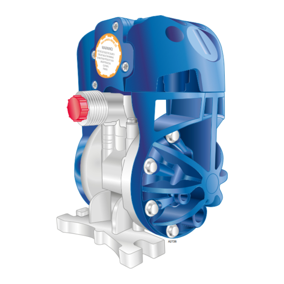
Duodos 20 PPS/PVT
Air-driven double diaphragm pump
EN
A2726
Please carefully read these operating instructions before use. · Do not discard.
The operator shall be liable for any damage caused by installation or operating errors.
The latest version of the operating instructions are available on our homepage.
Part number: 981452
Original operating instructions (2006/42/EC)
Version: BA DUO 015 05/20 EN
Advertisement
Table of Contents

Related Manuals for ProMinent Duodos 20 PPS


Summary of Contents for ProMinent Duodos 20 PPS
- Page 1 Assembly and operating instructions Duodos 20 PPS/PVT Air-driven double diaphragm pump A2726 Please carefully read these operating instructions before use. · Do not discard. The operator shall be liable for any damage caused by installation or operating errors. The latest version of the operating instructions are available on our homepage.
- Page 2 Supplemental directives General non-discriminatory approach In order to make it easier to read, this document uses the male form in grammatical structures but with an implied neutral sense. The document is always aimed equally at women, men and gender-neutral persons. We kindly ask readers for their under‐ standing in this simplification of the text.
-
Page 3: Table Of Contents
Table of contents Table of contents Function and identification............ 4 1.1 Function................ 4 1.2 Nameplate and identification........5 Safety and responsibility............6 2.1 Labelling of Warning Information........6 2.2 User qualification............8 2.3 Intended use..............8 2.4 General safety information on the Duodos....9 2.4.1 Safety information on the medium to be pumped and the diaphragm............. -
Page 4: Function And Identification
Function and identification Function and identification 1.1 Function A2984 Fig. 1: Duodos: Air-driven double diaphragm pump. The Duodos is an air-driven double diaphragm pump. The Duodos is run-dry safe and self-priming. The pump capacity of the double diaphragm pump can be con‐ trolled by changing the pressure in the air supply. -
Page 5: Nameplate And Identification
[INT] = input / [Ext.] = output Dimensions/ thread, Identification and material Type Pump capacity Seals Slide rod Part no. Duodos 20 PPS 0 ... 20 l/min EPDM Corrosion-proof steel 1103381 Duodos 20 PVT 0 ... 20 l/min PTFE 1103378 Hastelloy ®... -
Page 6: Safety And Responsibility
Safety and responsibility Safety and responsibility 2.1 Labelling of Warning Information Introduction These operating instructions provide information on the technical data and functions of the product. These operating instructions pro‐ vide detailed warning information and are provided as clear step- by-step instructions. - Page 7 Safety and responsibility Type of information Hints on use and additional information. Source of the information. Additional measures. Denotes hints on use and other useful informa‐ – tion. It does not indicate a hazardous or dam‐ aging situation.
-
Page 8: User Qualification
Safety and responsibility 2.2 User qualification WARNING! Danger of injury with inadequately qualified per‐ sonnel The operator of the system / equipment is respon‐ sible for ensuring that the qualifications are ful‐ filled. If inadequately qualified personnel work on the unit or loiter in the hazard zone of the unit, this could result in dangers that could cause serious injuries and material damage. -
Page 9: General Safety Information On The Duodos
Safety and responsibility 2.4 General safety information on the Duodos 2.4.1 Safety information on the medium to be pumped and the diaphragm Danger from hazardous substances! Please ensure when handling hazardous substances that you have read the latest material safety data sheets provided by the manu‐ facturer of the hazardous substances. -
Page 10: Safety Information On Ambient Conditions
Safety and responsibility 2.4.2 Safety information on ambient conditions Fig. 6: Ambient conditions Compressed air Before working on the double diaphragm pump, check whether it is necessary to close the compressed air lines and vent the double diaphragm pump. Before undertaking any maintenance and repair work, close off the compressed air supply, discharge the compressed air and detach the air supply line from the double diaphragm pump. -
Page 11: Transport And Storage
Transport and storage Transport and storage User qualification, transport and storage: trained user Ä Chapter 2.2 ‘User qualification’ on page 8 . WARNING! Danger from hazardous substances! Possible consequence: Fatal or very serious inju‐ ries. Please ensure when handling hazardous sub‐ stances that you have read the latest safety data sheets provided by the manufacture of the haz‐... -
Page 12: Assembly Of The Pump
Assembly of the pump Assembly of the pump Permissible ambient conditions User qualification, installation: trained and qualified personnel Ä Chapter 2.2 ‘User qualification’ on page 8 . Observe the permissible ambient conditions. Tab. 4: Permissible ambient conditions for operation All versions: - 10 °C ... - Page 13 Assembly of the pump Recommended installation max. 7 bar Compressed air input Liquid output OPTION Liquid input OPTION OPTION Outlet drainage valve Inlet drainage Liquid valve input A2727 Fig. 7: Recommended installation WARNING! Protect the pump from overload: Install a relief valve in the discharge line.
-
Page 14: Fastening The Double Diaphragm Pump
Assembly of the pump 4.1.1 Fastening the double diaphragm pump Correct securing of the device Only switch the device on if it has been properly fastened to the ground or its holding fixture. The system operator is responsible for ensuring that the ground and the fittings can hold the device safely and under all operating conditions. -
Page 15: Compressed Air Supply
Assembly of the pump 4.4 Compressed air supply Compressed air supply INFO: Suitable compressed air supply. The system operator is responsible for the provision of a suitable compressed air supply. When doing so, observe ISO 8573. Connect the double diaphragm pump to a compressed air supply in accordance with the current state of the art (ISO 8573-1). -
Page 16: Operation Of The Double Diaphragm Pump
Operation of the double diaphragm pump Operation of the double diaphragm pump Ä Chapter 2.2 User qualification, operation: instructed user ‘User qualification’ on page 8 . The double diaphragm pump is fully integrated into the system installed by the operator and is then controlled from this system. It is not possible to operate the double diaphragm pump directly. -
Page 17: Checking Tightening Torque Prior To Commissioning
Checking tightening torque prior to commissioning Checking tightening torque prior to commissioning User qualification, pre-commissioning checks: trained qualified Ä Chapter 2.2 ‘User qualification’ on page 8 . personnel A2729 Fig. 9: Permanent tightness: Check the tightening torque prior to commissioning, in the sequence shown in Fig. 9 . Prior to commissioning, check that the Check the tightening torque of the screws 1 ... -
Page 18: Commissioning
Commissioning Commissioning Ä Chapter 2.2 User qualification, commissioning: trained user ‘User qualification’ on page 8 . Check the fastening elements are cor‐ Check that all fastening elements with sealing rings are cor‐ rectly seated rectly seated before commissioning the double diaphragm pump. -
Page 19: Priming
Commissioning 7.2 Priming To start the double diaphragm pump, open the air valve by approximately a 1/2 ... 3/4 turn. INFO: Cavitation. Cavitation has occurred if opening the air valve causes the stroke rate of the double diaphragm pump to increase, but not the flow volume passing through the double diaphragm pump. -
Page 20: Troubleshooting And Fault Elimination
Troubleshooting and fault elimination Troubleshooting and fault elimination User qualification, troubleshooting and fault elimination: trained Ä Chapter 2.2 ‘User qualification’ qualified personnel on page 8 . The pump is not working. Cause: Recommended measure: The outlet valve on the discharge side is not Open the discharge valve on the discharge side. - Page 21 Troubleshooting and fault elimination The flow volume is reducing. Cause: Recommended measure: The air pressure is low. Check the compressor and the configuration of the air line. The air lines or additional equipment are Check and clean the air line and the auxiliary equipment. blocked with foreign bodies.
- Page 22 Troubleshooting and fault elimination Air bubbles in the feed chemical. Cause: Recommended measure: The diaphragm is faulty. Remove and check the pump and replace the dia‐ phragm. The suction hose is loose or broken. Fasten or replace the suction hose. Leaks or air pressure fluctuating between 3 ...
-
Page 23: Maintenance Of The Double Diaphragm Pump
Maintenance of the double diaphragm pump Maintenance of the double diaphragm pump User qualification, maintenance: trained and qualified per‐ Ä Chapter 2.2 ‘User qualification’ on page 8 . sonnel WARNING! Danger from hazardous substances! Possible consequence: Fatal or very serious inju‐ ries. -
Page 24: Maintenance Of The Diaphragm
Maintenance of the double diaphragm pump 9.1 Maintenance of the diaphragm A2731 Fig. 10: Maintenance of the diaphragm Cover with 4 screws Screws (8 no.) Directional valve with 4 screws Diaphragm O-rings O-rings Cover of the diaphragm... - Page 25 Maintenance of the double diaphragm pump WARNING! Danger from hazardous substances! Possible consequence: Fatal or very serious inju‐ ries. Please ensure when handling hazardous sub‐ stances that you have read the latest safety data sheets provided by the manufacture of the haz‐ ardous substance.
- Page 26 Maintenance of the double diaphragm pump A2991 Fig. 11: Replacing the diaphragm. Remove the worn diaphragm (6), drawing the diaphragm off the slide rod (8) to the side. Clean the seating surfaces in the housing. Push the recess (9) of the new diaphragm into the correct position on the slide rod (8).
-
Page 27: Maintenance Of The Slide Rod
Maintenance of the double diaphragm pump 9.2 Maintenance of the slide rod A2732 Fig. 12: Maintenance of the slide rod Rectangular O-ring Sleeve Holes for installation tool O-ring Slide rod WARNING! Danger from hazardous substances! Possible consequence: Fatal or very serious inju‐ ries. -
Page 28: Maintenance Of The Ball Valves
Maintenance of the double diaphragm pump Decontaminate the pump. Refer to the material safety data sheet for the feed chemical. Dismantle the pump, as described in Ä Chapter 9.1 ‘Mainte‐ nance of the diaphragm’ on page 24 . Proceed as follows as soon as the Remove the slide rod (5) from its housing by pulling on one slide rod is visible: end of the slide rod. - Page 29 Maintenance of the double diaphragm pump A2734 Fig. 13: Maintenance of the ball valves Remove the screws (1 ... 6) to remove the directional valve. Mark the alignment of the directional valve. Remove the inlet and outlet connectors. Note the alignment of the connecting pieces.
- Page 30 Maintenance of the double diaphragm pump Open the suction line of the double diaphragm pump ð Now the double diaphragm pump can pump again Check all connectors for leak-tightness...
-
Page 31: Disposal Of Used Parts
Decontaminate the device before returning it for repair. To do so, remove all traces of hazardous substances. Always observe the material safety data sheets for the medium being pumped. A current Declaration of Decontamination is available to download on the ProMinent GmbH website. -
Page 32: Technical Drawing
Technical drawing Technical drawing III. A2735 Fig. 14: Dimensions, inlets and outlets. Medium, 1/4" BSP/ NPT (F), 3/4” NPT (M). II. Compressed air, outlet III. Compressed air, inlet, (3/8" NPSM) IV. Medium, inlet, 1/4” BSP/ NPT (F), 3/4” NPT (M). Inch 5.59”... -
Page 33: Exploded Drawing Of The Pump
Technical drawing 11.1 Exploded drawing of the pump Exploded drawing – Duodos 20 A2736 Fig. 15: Exploded drawing – Duodos 20 Torque, tightening sequence 1 ... 8. -
Page 34: Spare Parts
Spare parts Spare parts INFO: Ordering address for spare parts and accessories: The cur‐ rent address for ordering spare parts and accessories can be found on the manufacturer’s homepage ProMinent GmbH. 12.1 Repair set, air valve with sensor A2982 Fig. 16: Repair set, air valve (1) with sensor (2) Tab. -
Page 35: Repair Set, Diaphragm With Valves
Spare parts 12.2 Repair set, diaphragm with valves A2983 Fig. 17: Repair set, diaphragm (3) with valve balls (4) and valve seats (1) with O-rings (2) Tab. 8: Parts list, repair set, diaphragm (3) with valve balls (4) and valve seats (1) with O-rings (2) Description Quantity Material... -
Page 36: Performance Curves
Performance curves Performance curves The performance curves are based on the pumping of water. Pump is filled. 80 mm suction head. A2738 Fig. 18: Performance curves Air consumption II. Pump capacity III. Feed chemical pressure... -
Page 37: Technical Data
Technical data Technical data Parameter Value Gear ratio: Maximum free flow: 20 l/min 5.28 US gal/min Air pressure, operating range: 1.5 ... 7 bar 22 ... 115 psi Solids in the feed chemical: < 2 mm < 3/32" Maximum suction lift: Dry: 2 m or 6 1/2”... -
Page 38: Declaration Of Conformity
In accordance with DIRECTIVE 2006/42/EC OF THE EUROPEAN PARLIAMENT AND OF THE COUNCIL, Appendix I, BASIC HEALTH AND SAFETY REQUIREMENTS, section 1.7.4.2. C. ProMinent GmbH Im Schuhmachergewann 5 - 11 D - 69123 Heidelberg, Germany, hereby declare that the product specified below complies with the... -
Page 39: Index
Index Index Error: The flow volume is reducing... . 21 Error: The pump is not working....20 Access for maintenance work . - Page 40 Index Maximum feed pressure ....5 Required tool ......23 Maximum free flow .
- Page 44 ProMinent GmbH Im Schuhmachergewann 5 - 11 69123 Heidelberg, Germany Telephone: +49 6221 842-0 Fax: +49 6221 842-419 Email: info@prominent.com Internet: www.prominent.com 981452, 2, en_GB © 2020...
Need help?
Do you have a question about the Duodos 20 PPS and is the answer not in the manual?
Questions and answers