Advertisement
Quick Links
®
advanced FLOW engineering
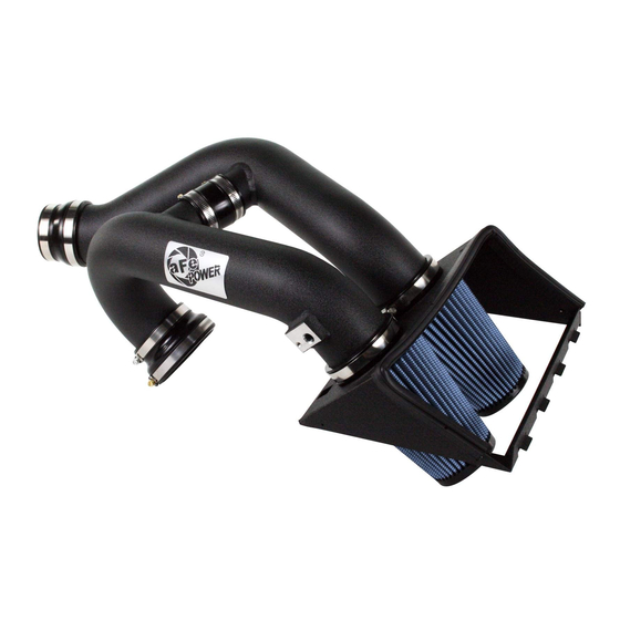
Magnum FORCE Stage-2 Air Intake System
Instruction Manual
P/N: 51-12642-1B / 54-12642-1B / 52-12642-1H
Make: Ford Model: F-150 Year: 2015-2021 Engine: V6-2.7L (tt) EcoBoost
Make: Ford Model: F-150 Year: 2015-2016 Engine: V6-3.5L (tt) EcoBoost
(CARB exempt 15-16 under D-550-28 only)
Advertisement

Subscribe to Our Youtube Channel
Related Manuals for aFe Power Magnum FORCE


Summary of Contents for aFe Power Magnum FORCE
- Page 1 ® advanced FLOW engineering Magnum FORCE Stage-2 Air Intake System Instruction Manual P/N: 51-12642-1B / 54-12642-1B / 52-12642-1H Make: Ford Model: F-150 Year: 2015-2021 Engine: V6-2.7L (tt) EcoBoost Make: Ford Model: F-150 Year: 2015-2016 Engine: V6-3.5L (tt) EcoBoost (CARB exempt 15-16 under D-550-28 only)
- Page 2 ® • Please read the entire instruction manual before proceeding. • Ensure all components listed are present. • If you are missing any of the components, call customer support at 951-493-7100. • Ensure you have all necessary tools before proceeding. •...
- Page 3 C1/C2 aFepower.com Page 3...
- Page 4 ® REMOVAL Figure A Refer to Figure A for steps 1-4 Step 1: Disconnect the Manifold Air Pressure (MAP) sensor plug from stock airbox. 1 Step 2: Loosen the OE intake clamps using an 8mm nut driver from the left and right side runners. 2 Step 3: Unclamp the top portion of the OE airbox.
- Page 5 REMOVAL Figure B Refer to Figure B for step 5 Step 5: Carefully remove plastic wire harness clips from back edge of lower airbox. Page 5 aFepower.com...
- Page 6 ® INSTALL Figure C Refer to Figure C for steps 6-7 Step 6: Install aFe housing and fasten clips. Step 7: Insert filters and place clamps loosely. Page 6...
- Page 7 INSTALL Figure D Refer to Figure D for steps 8-9 Step 8: Remove the MAP sensor from the OE intake 1/4 turn counter-clockwise. Step 9: Install the MAP sensor on the rear aFe intake tube using the provided grommet. The grommet can be held inside the tube to give support while inserting.
- Page 8 ® INSTALL Figure E Refer to Figure E for steps 10-14 Step 10: Install the small straight coupling on the cross over tube, install clamps, but do not tighten. Step 11: Fit tubes into the remaining couplers. Adjust for best fit and tighten all clamps. Step 12: Connect sensor harness.
- Page 9 INSTALL Vent insert installation: Figure F Refer to Figure F for Step 15 (These procedures should be done with the inlet tubes installed on the engine. It is shown off the vehicle for better illustration.) Step 15: Locate the o.e. plastic tube feeding the driver’s side turbo inlet. aFepower.com Page 9...
- Page 10 ® INSTALL Figure G Refer to Figure G for Step 16 Step 16: Locate the valve cover vent tube that feeds into driver’s side turbo inlet. It is not necessary to remove the engine cover. Page 10...
- Page 11 INSTALL Figure H Refer to Figure H for Step 17 Step 17: Note the release clip on the vent tube connectors. Apply pressure against the exposed tail and pull vent fitting off of the turbo inlet tube. It is not necessary to disconnect at the valve cover end.
- Page 12 ® INSTALL Figure I Refer to Figure I for Step 18 Step 18: Insert vent fitting with slash cut facing turbo inlet. It should not be a loose fit. It is direction dependent and must not rotate once installed. Page 12...
- Page 13 INSTALL Figure J Refer to Figure J for Steps 19-20 Step 19: Reconnect the vent fitting. It will snap over without having to release the plastic clip. Pull up slightly to confirm installation. Step 20: Installation is complete. Any codes can be cleared with a code reader or by disconnecting the battery.
- Page 14 ® Pro DRY S Air Filters Pro 5R Air Filters Pro-GUARD 7 Air Filters Pre-Filter Set P/N: 21-90069M P/N: 24-90069M P/N: 72-90069M P/N: 28-10213M Pro DRY S Restore Kit Pro 5R Restoe Kit Pro-GUARD 7 Restore Kit Intake System Cover P/N: 90-59999 P/N: 54-12188 P/N: 90-50501...
-
Page 15: Warranty
Warranty General Terms: • aFe warrants their products to be free from manufacturer’s defects due to workmanship and material. • This warranty applies only to the original purchaser of the product and is non-transferrable. • Proof of purchase of the aFe product is required for all warranty claims. •... - Page 16 ® ® advanced FLOW engineering, inc. 252 Granite Street Corona, CA 92879 TEL: 951.493.7155 • TECH: 951.493.7134 E-Mail:Tech@aFepower.com P/N: 06-80866...
Need help?
Do you have a question about the Magnum FORCE and is the answer not in the manual?
Questions and answers