Advertisement
Quick Links
advanced FLOW engineering
Instruction Manual
Make: BMW Model: M3/M4 (F80)
Make: BMW Model: M4 (F82/F83)
Make: BMW Model: M2 Competition (F87) Year: 2019-2020 Engine: L6-3.0L (tt) S55
Note: Includes M3 CS, M4 CS & GTS Models.
P/N: 77-46310
Year: 2015-2018 Engine: L6-3.0L (tt) S55
Year: 2015-2020 Engine: L6-3.0L (tt) S55
®
Advertisement

Related Manuals for aFe Power advanced FLOW engineering


Summary of Contents for aFe Power advanced FLOW engineering
- Page 1 ® advanced FLOW engineering Instruction Manual P/N: 77-46310 Make: BMW Model: M3/M4 (F80) Year: 2015-2018 Engine: L6-3.0L (tt) S55 Make: BMW Model: M4 (F82/F83) Year: 2015-2020 Engine: L6-3.0L (tt) S55 Make: BMW Model: M2 Competition (F87) Year: 2019-2020 Engine: L6-3.0L (tt) S55...
- Page 2 ® • Please read the entire instruction manual before proceeding. • Ensure all components listed are present. • If you are missing any of the components, call customer support at 951-493-7100. • Ensure you have all necessary tools before proceeding. •...
- Page 3 aFepower.com Page 3...
- Page 4 ® REMOVAL Figure A Refer to Figure A for Step 1. Step 1: Before installing your aFe module, you will have to place your vehicles ECU in sleep mode. In order to do this you will need to do the following: - If the engine is cold, open the hood, close the doors lock the car and wait 30 seconds.
- Page 5 REMOVAL Figure B Refer to Figure B for Steps 2-5. Step 2: Locate the TMAP 1 and MAP sensors 2 . The TMAP sensor is located driver side on charge pipe, the MAP sensor is located on top of the intake manifold, behind the charge-air cooler and under the expansion tank.
- Page 6 ® REMOVAL Figure C Refer to Figure C for Steps 6-7. Step 6: Pass the aFe module harness through frame brace. Step 7: Pop off the trim seal of the frame brace to allow more space. Page 6...
- Page 7 INSTALL Figure D Refer to Figures D for Steps 8-9. Step 8: Disconnect the MAP sensor, by pressing down on the locking tab and sliding the connector out of the sensor. Step 9: Locate the MAP sensor jumper harness on the aFe module. This is the longer harness with 4 wires in the connectors.
- Page 8 ® INSTALL Figure E Refer to Figure E for Steps 10-11. Step 10: Locate and disconnect the TMAP sensor, by pressing down on the locking tab and sliding the connector out of the sensor. Step 11: Locate the TMAP sensor jumper harness on the aFe module. This is the shorter harness with 3 wires in the connectors.
- Page 9 INSTALL Figure F Refer to Figure F for Steps 12-13. Step 12: Carefully route the switch cable behind steering wheel cover. Step 13: Mount the Switch on an open, flat surface Page 9 aFepower.com...
- Page 10 ® INSTALL Figure G Refer to Figure G for Steps 14-16. Step 14: Remove the two 10mm nuts holding the foot trim panel. Step 15: Route the switch cable through firewall and into the engine bay. Follow the main harness through the grommet into the firewall.
- Page 11 INSTALL Figure H Refer to Figure H for Steps 17-18. Step 17: Mount the module in a safe location, using the supplied Velcro strip. Then, secure the wires and module away from any extreme heat and moving parts, with the provided ties. Step 18: Re-install the windshield cover and expansion tank.
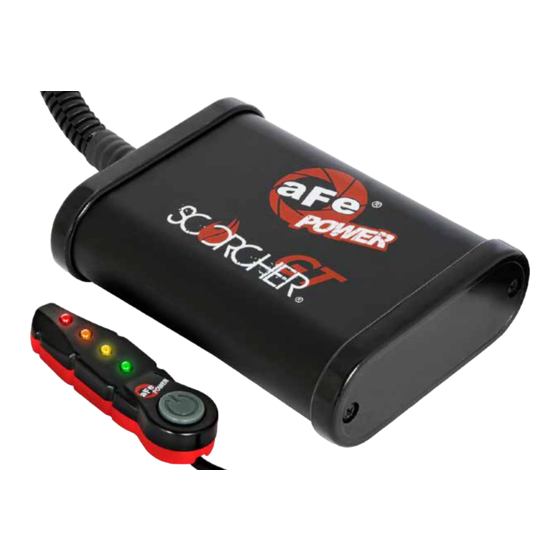
- Page 12 • Green LED: Stock • Yellow LED: Sport • Orange LED: Sport+ • Red LED: Race Use the grey button to select the desired setting. Power adjustments can be done at any moment. Thank you for choosing aFe POWER! Page 12...
- Page 13 Page left blank intentionally aFepower.com...
- Page 14 Page left blank intentionally aFepower.com...
- Page 15 Page left blank intentionally aFepower.com...
- Page 16 ® advanced FLOW engineering, inc. 252 Granite Street Corona, CA 92879 TEL: 951.493.7100 TECH: 951.493.7134 E-Mail:Tech@aFepower.com P/N: 06-80880...
Need help?
Do you have a question about the advanced FLOW engineering and is the answer not in the manual?
Questions and answers