Table of Contents
Advertisement
Quick Links
Advertisement
Table of Contents

Related Manuals for Tech Controllers EU-ML-12


Summary of Contents for Tech Controllers EU-ML-12
- Page 1 EU-ML-12...
-
Page 3: Table Of Contents
TABLE OF CONTENTS Safety ....................................5 System description................................6 III. Installing the Controller ..............................6 First startup .................................. 13 Main screen description ..............................14 Controller functions ..............................16 Operation mode ................................16 Zones .................................... 16 2.1. ON ..................................16 2.2. Set temperature .............................. - Page 4 4.14. Maximum humidity ............................33 4.15. Heat pump ............................... 34 4.16. Language ................................. 34 4.17. Factory settings ............................... 34 Service menu ................................34 Factory settings ................................ 34 Software version ..............................34 VII. Alarm list ..................................35 VIII. Software update ................................37 Technical data ................................
-
Page 5: Safety
I. SAFETY Before operating the device, please read the following instructions carefully. Failure to observe the instructions may cause personal injuries and damage the device. To avoid unnecessary errors and accidents, make sure that all persons operating the device have thoroughly familiarized themselves with the device operation and its safety functions. Please do not discard the manual and please make sure that it remains with the device when it is transferred. -
Page 6: System Description
II. SYSTEM DESCRIPTION The EU-ML-12 additional controller is a part of heating control system that enables expansion of the existing installation with additional zones. It has RS 485 and wireless communication. Its primary function is to maintain the preset temperature in each zone. - Page 8 An illustrative diagram explaining how to connect and communicate with the remaining equipment: CAUTION If the EU-WiFi RS, EU-505 or EU-WiFi L Internet module is connected to the EU-ML-12, then the emodul.eu application will display only the zones of the respective EU-ML-12 controller. If such a module is connected to...
- Page 10 Connection between controllers In the case of wired connection between devices: controllers (EU-L-12 and EU-ML-12), room controllers and panel, terminating resistors (jumpers) should be used at the beginning and end of each transmission line. The controller has a built-in terminating resistor, which should be set in the appropriate position: •...
- Page 11 Connection between the controller and the room controllers When connecting room controllers to the first controller, the jumpers on the controller and on the last of the room controllers are switched to the ON position. If the room controllers are connected to a controller located in the middle of the transmission line, the jumpers to the first and last controllers are switched to the ON position.
- Page 12 CAUTION If the panel is connected to the EU-ML-12, then this controller must be connected to the main EU-L-12 controller, and this panel must be registered in the following way: Menu → Fitter’s menu → Control panel →...
-
Page 13: First Startup
Step 4. Configure temperature sensors, room controllers In order for the EU-ML-12 controller to support a given zone, it must receive information about the current temperature. The simplest way is to use a wired or wireless temperature sensor (e.g. EU-C-7p, EU-C-mini, EU-CL-mini, EU-C-8r). However, if you wish to be able to change the set temperature value directly from the zone, you can use either room controllers: e.g. -
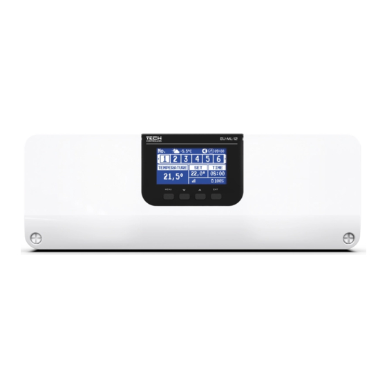
Page 14: Main Screen Description
CAUTION If the user wants to use these devices during operation, they must be connected and/or registered. V. MAIN SCREEN DESCRIPTION The control is carried out by means of buttons located under the display. 1. Controller display. 2. MENU button - enters the controller menu, confirming the settings. button - used to browse the menu functions, decrease the value of the edited parameters. - Page 15 4. Activated voltage-free contact the zone is overheated the zone is cooled 5. Current time 6. Information about the operating mode/schedule in the respective zone local schedule constant temperature G-1….G-5 global schedule 1-5 02:08 time-limited 7. Signal strength and battery status of the room sensor information 8.
-
Page 16: Controller Functions
VI. CONTROLLER FUNCTIONS Operation mode Menu Zones Controller settings Fitter's Menu Service menu Factory settings Software version OPERATION MODE This function enables activation of the selected operating mode. ➢ Normal mode – the preset temperature depends on the set schedule ➢... -
Page 17: Operation Mode
2.3. OPERATION MODE The user has the ability to view and edit the operating mode settings for the zone. • Local Schedule – Schedule settings that only apply to this zone • Global Schedule 1-5 – These schedule settings apply to all zones, where they are active •... -
Page 18: Controller Settings
After setting the schedule for all the days of the week, press the EXIT button and select the Confirm option with the MENU button. CAUTION The users can set three different time intervals in a given schedule (with an accuracy of 15 minutes). CONTROLLER SETTINGS 3.1. -
Page 19: Zones
4.1. ZONES In order for a given zone to be active on the controller display, a sensor must be registered in it. Menu Fitter's Menu Zones Room Sensor Zone... Set temperature Operation mode Outputs configuration Settings Actuators Window sensors Floor heating 4.1.1. -
Page 20: Settings
4.1.5. SETTINGS ➢ Weather control - the option to turn the weather control on/off. CAUTION • Weather control works only if in the Menu → Fitter's menu → External sensor, Weather control option was checked. • The external sensor menu is available after registering the sensor with L-12. ➢... -
Page 21: Actuators
4.1.6. ACTUATORS ➢ Settings • SIGMA - the function enables seamless control of the electric actuator. The user can set the minimum and maximum openings of the valve – this means that the degree of opening and closing of the valve will never exceed these values. -
Page 22: Window Sensors
4.1.7. WINDOW SENSORS ➢ Settings • ON - The function enables the activation of window sensors in a given zone (window sensor registration required). • Delay Time - This function allows setting the delay time. After the preset delay time, the main controller responds to the opening of the window and blocks heating or cooling in the respective zone. -
Page 23: Additional Contacts
➢ Operation mode • OFF – Selecting this option disables the floor heating mode, i.e. neither Floor Protection Comfort Mode are active. • Floor Protection – This function is used to keep the floor temperature below the set maximum temperature to protect the system from overheating. -
Page 24: Mixing Valve
Mixing valve The EU-ML-12 controller can operate an additional valve using a valve module (e.g. EU-i-1m). This valve has RS communication, but it is necessary to carry out the registration process, which will require you to quote the module number located in the rear of its housing, or in the software information screen). - Page 25 ➢ Valve Hysteresis - This option is used to set the valve setpoint temperature hysteresis. This is the difference between the preset temperature and the temperature at which the valve will start to close or open. Example: Valve preset temperature: 50°C Hysteresis: 2°C Valve stop: 50°C Valve opening: 48°C...
- Page 26 CAUTION This setting is not available in the Cooling Return Protection Modes. Heating curve - this is the curve according to which the set temperature of the controller is determined on the basis of the external temperature. In order for the valve to operate properly, the set temperature (downstream the valve) is set for four intermediate external temperatures: -20°C, -10°C, 0°C and 10°C.
- Page 27 • Room controller function - In this function, it is necessary to set whether the valve will close (Closing) or the temperature will lower (Lowering the room temperature) once it is heated. ➢ Proportionality coefficient – The proportionality coefficient is used to determine the valve stroke. The closer to the set temperature, the smaller the stroke.
- Page 28 → Always OFF - the pump is switched off permanently and the controller only controls the operation of the valve → Turned ON above the threshold - the pump turns on above the set switching temperature. If the pump is to be switched on above the threshold, the threshold pump switching temperature must also be set.
- Page 29 Example: Temperature - Set Time Weekly Control Monday ‐ 7 +5°C PRESET ‐ 14 ‐10°C ‐ 22 +7°C In this case, if the temperature set on the valve is 50°C, on Mondays, from 4 to 7 hours ‐ the temperature set on the valve will increase by 5°C, or to 55°C;...
-
Page 30: Master Module
2. Start the registration on the transmitting device (e.g. EU-ML-12, EU-M-12). 3. After the correct execution of steps 1 and 2, the wait prompt on the EU-ML-12 controller should change from "Registration step 1" to "Registration step 2", and on the registration of the transmitting device - “success”. Every step of the registration process is approx. -
Page 31: Internet Module
L to the controller, which are not included as standard in the controller. CAUTION When the Internet module is connected to the EU-ML-12 controller, the emodul.eu application will display only the zones of the given EU-ML-12 controller; when connected to the main EU-L-12 controller, the application will display all zones of the entire system. -
Page 32: Heating Stopping
Voltage-free contact The EU-ML-12 controller will activate the voltage-free contact (after counting down the delay time) when any of the zones has not reached the set temperature (heating – when the zone is underheated, cooling – when the temperature in the zone is too high). -
Page 33: Pump
Pump The EU-ML-12 controller controls the pump operation – it switches on the pump (after counting down the delay time) when any of the zones is underheated and when the floor pump option is enabled in the respective zone. When all zones are heated (the set temperature is reached), the controller switches off the pump. -
Page 34: Heat Pump
4.15. HEAT PUMP This is a dedicated mode for an installation operating with a heat pump, and enables optimal use of its capabilities. ➢ Energy saving mode – ticking this option will start the mode and more options will appear ➢... -
Page 35: Alarm List
VII. ALARM LIST Alarm Possible cause Troubleshooting Sensor defective (room sensor, floor Sensor short-circuited or defective - Check the correct connection of the sensor) sensor - Replace the sensor with a new one, Contact service if necessary. Lack of communication with wireless - No signal - Move the sensor/room controller to Sensor/Controller Alarm... - Page 36 ERROR – feedback - Master controller disabled - Check if the master controller is communication - Poor signal or no signal to master operating controller - Reduce the distance from the master - Defective RF module in the controller actuator - Call service.
-
Page 37: Software Update
VIII. SOFTWARE UPDATE To upload new software, disconnect the controller from the network. Insert the USB flash drive containing the new software into the USB port. Subsequently, connect the controller to the network while holding down the EXIT button. Hold down the EXIT button until you hear a single beep marking the start of uploading new software. - Page 38 EU DECLARATION OF CONFORMITY Hereby, we declare under our sole responsibility that EU-ML-12 manufactured by TECH STEROWNIKI, head‐quartered in Wieprz Biała Droga 31, 34‐122 Wieprz, is compliant with Directive 2014/53/EU of the European parliament and of the Council of 16 April 2014 on the harmonisation of the laws of the Member States relating to the making available on the market of radio equipment, Directive 2009/125/EC establishing a framework for the setting of ecodesign requirements for energy‐...
Need help?
Do you have a question about the EU-ML-12 and is the answer not in the manual?
Questions and answers