Table of Contents
Advertisement
Quick Links
Advertisement
Table of Contents

Related Manuals for BK Precision 5335C


Summary of Contents for BK Precision 5335C
- Page 1 5335C Power Meter User Manual...
-
Page 2: Safety Summary
Safety Summary The following safety precautions apply to both operating and maintenance personnel and must be followed during all phases of operation, service, and repair of this instrument. Before applying power to this instrument: • Read and understand the safety and operational information in this manual. •... - Page 3 You must ensure that each accessory you use with this instrument has a category rating equal to or higher than the instrument’s category rating to maintain the instrument’s category rating. Failure to do so will lower the category rating of the measuring system. Electrical Power This instrument is intended to be powered from a CATEGORY II mains power environment.
- Page 4 • In the presence of noxious, corrosive, or flammable fumes, gases, vapors, chemicals, or finely-divided particulates. • In relative humidity conditions outside the instrument’s specifications. • In environments where there is a danger of any liquid being spilled on the instrument or where any liquid can condense on the instrument.
-
Page 5: Compliance Statements
before touching any internal parts. Verify the voltage-sensing device is working properly before and after making the measurements by testing with known-operating voltage sources and test for both DC and AC voltages. Do not attempt any service or adjustment unless another person capable of rendering first aid and resuscitation is present. Do not insert any object into an instrument’s ventilation openings or other openings. - Page 6 Safety Symbols Description Symbol Indicates a hazardous situation which, if not avoided, will result in death or serious injury. Indicates a hazardous situation which, if not avoided, could result in death or serious injury. Indicates a hazardous situation which, if not avoided, will result in minor or moderate injury. Refer to the text near the symbol.
-
Page 7: Table Of Contents
Contents Contents Safety Summary ................................2 Compliance Statements ..............................5 Contents ....................................7 Features ................................9 Front Panel ..............................10 Rear Panel ..............................11 Input Power and Fuse Requirements ........................12 Power-up Sequence ............................12 Menu ....................................13 System Softkey ..............................13 System Menu .............................. - Page 8 Setting of Integral Measurement Configuration ....................40 Integration ..............................41 Remote Operation ................................. 42 RS-232 Interface ............................. 42 USB interface ..............................43 LAN interface ..............................43 Specifications ..................................45 Specifications ............................46 Specifications (cont.) ........................48 Specifications (cont.) ........................50 Routine Maintenance ................................
-
Page 9: Features
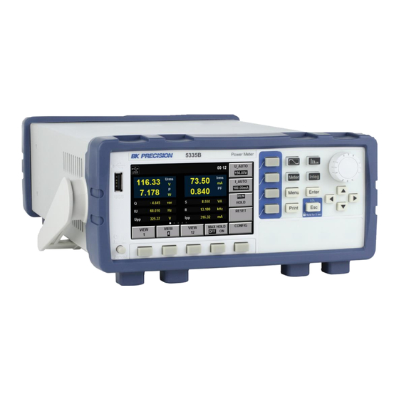
General Information The BK5335C power meter measures AC and DC inputs up to 600Vrms and 20Arms from DC to 100kHz. It measures voltage, current, power, frequency, power factor, phase and harmonic parameters up to the 50th order. Remote control is available over USB, RS232 and LAN communication interfaces. Voltage and current measurement precision is nominally 0.1%. -
Page 10: Front Panel
General Information 1.2 Front Panel illustrates and describes the front panel of the 5335C. lists the functions available from the front Figure 1.1 Table 1.1 panel buttons. Item Description Item Description Power Button Rotary Knob 4.3” LCD Arrow Keys Soft-keys... -
Page 11: Rear Panel
General Information 1.3 Rear Panel The rear panel includes the connections for current and voltage. The internal shunt is here and should be connected in series with the load. See Figure 1.2. Item Description Item Description LAN Connector AC Line USB Connector External Current Sensor RS-232 Connector... -
Page 12: Input Power And Fuse Requirements
General Information 1.4 Input Power and Fuse Requirements 110V ± 10% or 220V ± 10% AC Voltage 47Hz – 63Hz Frequency An AC input fuse is necessary when powering the instrument. See Table 1.2. Table 1.2 Required Fuses Figure 1.3 Fuse Holder 1.4.1 Fuse Replacement 1. -
Page 13: Menu
Note: When contacting B&K, use the serial number on the label. 2.4 Communication Configuration Menu Available remote interfaces are RS-232, USBTMC, and LAN. For details about commands and use of the remote interfaces, see the programming manual. The manual is found on the product page of the 5335C at www.bkprecision.com... - Page 14 Menu Item Description SYSTEM INFO System details, Model, Serial, etc… COMM CONFIG Setup the communication interfaces SYSTEM CONFIG Set date, time, beep and brightness SELF TEST Perform a self diagnostic INITIAL Reset device settings Figure 2.2 System Info Screen 2.4.1 RS-232 This interface support 6 common baudrates: 4800, 9600, 19200, 38400, 57600, 115200.
-
Page 15: System Configuration Menu
Menu Figure 2.4 COMM Configuration - USB 2.4.3 LAN The LAN (Ethernet) interface may be configured as either DHCP or static. Use the arrow keys to select the IP Mode field. When DHCP is selected, the current IP, subnet, and gateway are shown on screen (Figure 2.6). -
Page 16: Self Test
Menu Figure 2.6 COMM Configuration - LAN (DHCP) Figure 2.7 COMM Configuration - LAN (Manual (static)) 2.6 Self Test The unit has a built in self test. This function tests the LEDs, the screen and some of the internal electronics, Figure 2.9. - Page 17 Menu Figure 2.8 System Config Menu Figure 2.9 System Self Test 2.8.1 Setup Info Menu From the top level after pressing the “Menu” key, the second soft-key is “Setup”. This menu contains settings for configuring the measurement system of the meter. Setting such as averaging, external sensors, update speed and similar are configured under this menu.
- Page 18 Menu Figure 2.10 System Init Menu Item Description Setup Info Setup information: Averaging, Sync Source, Filters and sensor config Average Set Setup averaging External Sensor Enable and setup the external sensor inputs Other Set Setup the remaining settings Inrush Set Set the timing and trigger levels for measuring inrush Figure 2.11 Setup Info Menu the value displayed after the (n-1)th index averaging...
-
Page 19: External Sensor Setup
Menu Item Description State The state of the average function, On or Off. Type Exp or Line. Exp enables index averaging, and Line enables linear averaging. Tcontrol Sets averaging to being either a rolling of repeating average. Count EXP averaging attenuation constant, or LINE average count. Figure 2.12 Measured value The number of values in the average set (1-64) - Page 20 Menu Figure 2.13 Ratio Set Menu Item Description Sync Source Select the synchronization source: U/I/OFF. The overall interval of the signal voltage, current or data updating cycle can be selected as the synchronization source for measurement. Freq Filter Set the status of the frequency filter. When “ON” is selected, the frequency filter is turned on. When “OFF”...
- Page 21 Menu 5335C is specified as the times of the crest value which can be input under the rated input conditions. The crest factor...
-
Page 22: Inrush Measurement Setup
Menu CF3 or CF6 can be selected in the interface “Menu > SETUP > OTHER SET”. See for more details. Chapter 3 2.11 Inrush Measurement Setup Feature not currently implemented. Setting Description State ON/OFF - Enable or disable inrush measurement. Trig Level(A) The current level to triggin inrush measurement Delay Time(ms) The hold off time following a trigger to start measurement... -
Page 23: Ratio Setup
Menu 2.13 Ratio Setup This setting has the effect of scaling the measured value of the current and voltage. For example, a 116V signal becomes 232V when the “Voltage Ratio” is set to 2. The Ranges are not effected by this setting, so the 150V range is still shown and used. -
Page 24: Measurement Setup
Measurement Setup Central to setting the proper range of the instrument is the Crest Factor. Crest factor is the ratio of the peak value of a waveform to the RMS value of the waveform. For example, a perfect sine wave crest factor RMS value is 0.707*Peak. The crest factor is the inverse of the normalized RMS value, 0.707 = 1.414. -
Page 25: Auto Voltage And Current Range
Measurement Setup Note: Measurement accuracy is improved by minimizing the range for a given input signal. 3.4 Auto Voltage and Current range The measurement range adjusts automatically according to the input signal, and uses same ranges as in Fixed range mode. -
Page 26: Filter And Crest Factor Setting
Measurement Setup Figure 3.1 Measurement Timing 3.6 Filter and Crest Factor Setting 1. Select Menu → SET UP → OTHER SET and enter the OTHER configuration page. 2. Press to select the parameter to be configured (blue font background), and then press the soft key corresponding to the parameter on the right to set the required value, as shown in the Figure 3.2. - Page 27 Measurement Setup Setting Description Sync Source Synchronization Source, the source used to determine the measurement interval. May be set to voltage (U), current (I) or turned off. Freq Filter Enable or disable the Frequency Filter. Line Filter Enable or disable the Line Filter. Crest Factor Set the crest factor to 3(CF3), or 6 (CF6) (See Section 3.1)
-
Page 28: Index Averaging
Measurement Setup 3.10 Index averaging �� − �� �� ��−1 �� = �� �� ��−1 �� �� The value displayed after the nth index averaging, ( �� , the value displayed after the first averaging, �� is equal to M1) ��... -
Page 29: Meter Display
Meter Display The 5335C has 3 configurable display formats. Each format also allows for 5 different configured sets of measurement. 1 large and 6 small, 4 large and 6 small, or 12 small measurements may be displayed. See Figures 4.1,4.2,4.3. - Page 30 Meter Display Figure 4.2 4 main measurements Figure 4.3 12 main measurements...
-
Page 31: Waveform Display Function
Waveform Display Function The 5335C power meter displays waveform representations of the sampled data measured. This function is designed to be similar to an oscilloscope with many of the typical functions of oscilloscopes available, like trigger, run/stop and single trigger. The capture of data is not limited to that displayed onscreen, the measurement interval is also involved. For example, measuring a 15Hz signal with the interval set to 0.1s does not allow for stable measurement of the frequency. -
Page 32: Trigger Setup
Waveform Display Function Auto mode waiting for a trigger Auto? Single mode waiting for a trigger Trig? Capture stopped. Reached either by pressing “stop” or completing a single mode capture Stop 5.2 Trigger Setup When you need to enable the trigger function, you should select the trigger source, trigger mode, trigger slope and other trigger-related configuration. - Page 33 Waveform Display Function NOTE: When the voltage higher than 0-3.3V is applied on the external signal input interface (Synchronous), the instrument may be damaged. refers to the width of the high or low trigger level, at least 1����. Minimum pulse width refers to the delay between the appearance of the trigger level and the response of CPU, within Trigger delay time (1����...
-
Page 34: Harmonic Measurement Function
Harmonic Measurement Function With the 100kHz bandwidth, the 5335C power meter can realize harmonic measurement of high speed and wide dynamic range. The voltage, current, active power, reactive power, phase of harmonics and total harmonic distortion (THD) factor can be tested in harmonic measurement mode. Display of harmonic parameters is either in list or bar chart form for clear analysis of test results. -
Page 35: List Mode
Harmonic Measurement Function Figure 6.2 Bar Graph Data 6.2 List Mode Enter this mode by pressing the button (if not in the harmonic mode already), then select “LIST” from the on- screen soft-keys. This list is used for showing the voltage, current, active power, reactive power, phase and total harmonic distortion (THD) factor of different harmonics. - Page 36 Harmonic Measurement Function Function Description U(V) Voltage I(mA) Current P(mW) Power Q(mvar) Reactive Power S(mVA) Apparent Power PF() Power Factor ∘ Phase difference of k-order harmonic voltage and harmonic current ��UI( ∘ Phase difference of harmonic voltage U(k) and fundamental U(1) ��UU( ∘...
- Page 37 Harmonic Measurement Function 6.3.2 Distortion factor Distortion is either calculated relative to the fundamental (%f) or to the total signal (%r). Internally, the 5335C calculates according to the following equations: Measurement function �� ( �� Harmonic distortion factor of voltage ��...
-
Page 38: Integral Operation Function
(sold) or consuming (buying) directions. The 5335C power meter can be used for integral operation of the current and power of the input unit. Technical indicators can be calculated. In addition, the range can be switched automatically in the Buy and Sell modes according to the input level so as to accurately complete integrate measurement. -
Page 39: Integral Measurement Display Information
Integral Operation Function Parameter Description V_RANGE Voltage range setting: press the soft key corresponding to this parameter to set the voltage range. A_RANGE Current range setting: press the soft key corresponding to this parameter to set the current range. RUN/HOLD Run/hold: press the soft key corresponding to this parameter to run or hold the integral function. -
Page 40: Specification
Integral Operation Function • Active power integralIn watt hour, displayed as WP (watt hours, the sum of positive and negative watt hours), WP+ (the consumption of positive watt hours) and WP- (the negative watt hours of feedback power). • Current integralIn q, displayed as q (ampere hours, the sum of positive and negative ampere hours), q+ (the con- sumption of positive ampere hours) and q- (the negative ampere hours of feedback power) •... -
Page 41: Setting Of Integral Measurement Configuration
Integral Operation Function NOTE: In addition to the above items, other settings (such as self-testing and date/time setting) or operations with influence on the integral cannot be executed; otherwise, errors may be caused. 7.3 Setting of Integral Measurement Configuration You can set the start mode, stop mode, automatic zero setting, automatic calibration, watt-hour integration, current integration and other parameters of integral measurement. -
Page 42: Integration
Integral Operation Function used for selecting the current integration mode. Options of the current integration mode are as q type follows: Effective value; Calibration to the average rectified value of the effective value. Simple averaging; Average rectified value; AC component 7.4 Integration When the integral measurement function is enabled, you can keep the current integral information and carry out the following operations: exit, start and stop. -
Page 43: Remote Operation
Remote Operation There are four types of communication interfaces available: USB, Ethernet, and RS232.You can choose any one of them to communicate with a PC. 8.1 RS-232 Interface RS232 interface:use a cable with two COM interface (DB9) to connect power meter and PC. It can be activated by menu key on the front panel. -
Page 44: Usb Interface
PCs connected to the Internet. If the network is provided with an avail- able DHCP server, the server will automatically assign information (IP address, subnet mask and default gateway) to PCs and other equipment connected to the network. 5335C cannot... - Page 45 DHCP unless the network is provided with a DHCP server. Please ask your network ad- ministrator DHCP if DHCP is available. • IP Address: IP addresses assigned to 5335C can be set. Default address is 192.168.000.000. • IP address refers to ID assigned by the network to each equipment (Internet or enterprise Intranet).
- Page 46 Specifications The specifications listed below are valid and specified for the following conditions: • Warm up time of 30 minutes • Ambient temperature - 23 ± 5 ∘ • Relative humidity 30 to 75%...
-
Page 47: Specifications
Power Meter 5335C Specifications Specifications are subject to the following conditions Temperature: 23±5° C, humidity: 30 to 75% RH. Warm-up time: 30 minutes 5335C General Measurement Specifications Peak to peak, Maximum, Minimum, Average_rms, Average_rectified, DC, Voltage, Current Crest factor (current), Inrush (current) - Page 48 Power Meter 5335C www.bkprecision.co...
-
Page 49: Specifications (Cont.)
Power Meter 5335C Specifications (cont.) Current Measurement Accuracy and Ranges CF= 3:5 mA, 10 mA, 20 mA, 50 mA, 100 mA, 200 mA, 0.5 A, 1 A, 2 A, 5 A, 10 A, 20 A Direct input range CF= 6:2.5 mA, 5 mA, 10 mA, 25 mA, 50 mA, 100 mA, 250 mA, 0.5 A, 1 A, 2.5 A, 5 A, 10 A CF = 3: 2.5 V, 5 V, 10 V... - Page 50 Power Meter 5335C...
- Page 51 Power Meter 5335C Specifications (cont.) Harmonic Measurement Parameters Measurement method PLL synchronization Frequency range PLL frequency source range 10 Hz to 1.2 kHz (typical) FFT data length 1024 Window function Rectangle Fundamental frequency (Fund. freq.) 10 Hz to 75 Hz...
- Page 52 Power Meter 5335C...
-
Page 53: Routine Maintenance
10.2 Error Information References The 5335C power meter has a detailed error and prompt information function, so as to help the user to easily carry out positioning and measurement during measurement and use. This section describes all error information of the 5335C power meter as well as error causes and disposals. - Page 54 Routine Maintenance Error information explanation usb is not detected No USB peripheral is found. Error description No USB peripheral is inserted. Possible cause Insert the U disc type USB peripheral and then copy the Disposal screen. Save screen fail The screen is not saved successfully. Error description USB is disconnected.
- Page 55 Routine Maintenance Cal zero fail Zero calibration fails. Error description Communication abnormality Possible cause Check the communication cable. Disposal...
-
Page 56: Daily Maintenance
Routine Maintenance 10.3 Daily maintenance Introduce basic maintenance in daily use of equipment. Such as cleaning, self-maintenance allowed to be performed by the user, etc. 10.3.1 Equipment cleaning Use dry cloth or slightly wet cloth to gently wipe the equipment. Do not arbitrarily wipe the inside of the instrument. Cut off the power supply before cleaning. -
Page 57: Service Information
Service Information Warranty Service: Please go to the support and service section on our website at bkprecision.com to obtain an RMA #. Return the product in the original packaging with proof of purchase to the address below. Clearly state on the RMA the performance problem and return any leads, probes, connectors and accessories that you are using with the device.
Need help?
Do you have a question about the 5335C and is the answer not in the manual?
Questions and answers