Table of Contents
Advertisement
Quick Links
Advertisement
Table of Contents

Related Manuals for BK Precision 5335C


Summary of Contents for BK Precision 5335C
- Page 1 5335C Power Meter User Manual...
- Page 2 SAFETY SUMMARY Safety Summary The following safety precautions apply to both operating and maintenance personnel and must be followed during all phases of operation, service, and repair of this instrument. Before applying power to this instrument: • Read and understand the safety and operational information in this manual. •...
- Page 3 You must ensure that each accessory you use with this instrument has a category rating equal to or higher than the instrument’s category rating to maintain the instrument’s category rating. Failure to do so will lower the category rating of the measuring system. Electrical Power This instrument is intended to be powered from a CATEGORY II mains power environment.
- Page 4 SAFETY SUMMARY this instrument may be outside specifications if the instrument is used in non-office-type environments. Such environments may include rapid temperature or humidity changes, sunlight, vibration and/or mechanical shocks, acoustic noise, electrical noise, strong electric fields, or strong magnetic fields. Do not operate instrument if damaged If the instrument is damaged, appears to be damaged, or if any liquid, chemical, or other material gets on or inside the instrument, remove the instrument’s power cord, remove the instrument from service, label it as not to be...
- Page 5 specified in this manual or on the back of the instrument. Failure to do so may damage the instrument, lead to a safety hazard, or cause a fire. Failure to use the specified fuses will void the warranty. Servicing Do not substitute parts that are not approved by B&K Precision or modify this instrument. Return the instrument to B&K Precision for service and repair to ensure that safety and performance features are maintained.
-
Page 6: Ce Declaration Of Conformity
SAFETY SUMMARY CE Declaration of Conformity This instrument meets the requirements of: EMC Directive • EN 61326-1 2006 • EN 61000-3-2-2006 • EN 61000-3-3:1995... -
Page 7: Safety Symbols
Safety Symbols Refer to the user manual for warning information to avoid hazard or personal injury and prevent damage to instrument. Electric Shock hazard Alternating current (AC) Chassis (earth ground) symbol. Ground terminal On (Power). This is the In position of the power switch when instrument is ON. -
Page 8: Table Of Contents
Contents Safety Summary ............................iii CE Declaration of Conformity ........................vii EMC Directive ............................. vii Safety Symbols ............................viii Contents ............................... 9 General Information ..........................11 Features ............................11 Front Panel ............................2 Rear Panel Summary ........................3 Measurement Connection Setup ..................... 3 Wiring External Current Sensors ...................... - Page 9 3.2.2 Auto Range ..........................13 Measurement Interval ........................14 Filter and Crest Factor Setting ....................... 15 3.4.1 Filter ............................16 Averaging Function ........................17 3.5.1 Index averaging .......................... 17 3.5.2 Linear averaging ......................... 18 3.5.3 Averaging function ........................18 3.5.4 Measurement function in harmonic measurement ..............
-
Page 10: General Information
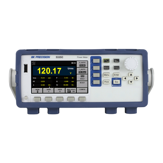
Chapter 1 General Information Note: The contents of this manual and included specifications are subject to change go to for the latest version. (Manual version–2017-10-09 ) Figure shows a schematic Diagram of Front Panel of BK5335C Series Power Meter and Diagram of Key Functions. -
Page 11: Front Panel
CHAPTER 1. GENERAL INFORMATION Front Panel Figure 1.1: Front Panel Power ButtonRotary Knob 4.3” LCDArrow Keys USBSoft-keys Main FunctionsSoft-keys Menu, Enter, ESCPrint (Screen Capture) Name and function Waveform Display key: press to view waveforms. See Chapter Harmonic Measurement key: For viewing harmonic measurements. See Chapter Basic Measurement key: The normal measurement screen. -
Page 12: Rear Panel Summary
CHAPTER 1. GENERAL INFORMATION Image Save key: press to save a hardcopy of the screen to the USB host port on the front panel. Rear Panel Summary Figure 1.2: Rear View LAN Connector AC Line USB Connector External Current Sensor RS-232 Connector Voltage Input Synchronization BNC... - Page 13 CHAPTER 1. GENERAL INFORMATION Figure 1.3: Current terminal cover Figure 1.4: Low Current Wiring Setup Figure 1.5: High Current Wiring Setup...
-
Page 14: Wiring External Current Sensors
CHAPTER 1. GENERAL INFORMATION Figure 1.6: External Sensor Interface: DE-9 Connector Pin # Description +12 V -12 V Signal GND Voltage Current Table 1.1: External Sensor Connector Pinout Wiring External Current Sensors This power meter accepts a wide range of external current sensors. Measurement is achieved by applying a scaling factor to the voltage sensed at the external sensor input. -
Page 15: Power Up
An AC input fuse is necessary when powering the instrument. Refer to Table for the fuse requirements. Model Fuse Specification (110 V) Fuse Specification (220 V) 5335C T 10 A, 250 V T 6.3 A, 250 V Table 1.2: Required Fuses 1.6.2.1 Fuse Replacement 1. -
Page 16: Menu
Chapter 2 Menu Configuration of system-wide settings is done from the “Menu”. Pressing the button enters the configuration/system menu, Figure 2.1. From the main menu, the soft-keys at the bottom of the screen provide access to the configuration screens. See Table SYSTEM menu From the system menu, system-wide functions are set and viewed. -
Page 17: Setup Menu
CHAPTER 2. MENU Figure 2.2: System Menu Figure 2.3: Calibration Menu Function Description SYSTEM INFO System details, Model, Serial, etc... COMM CONFIG Setup the communication interfaces SYSTEM CONFIG Set date, time, beep and brightness SELF TEST Perform a self diagnostic INITIAL Reset device settings SETUP Menu... - Page 18 CHAPTER 2. MENU Figure 2.4: Ratio Setup Menu Figure 2.5: Information Screen is still shown and used. Use the arrow keys to move between parameters and digits. Use the knob to change the value of the selected digit. To commit the setting change, press the button.
-
Page 19: Under The Setup Menu
CHAPTER 2. MENU Under the setup menu External Current Sensor Figure 2.6: Ratio Set Menu Figure 2.7: Ratio Set Menu Figure 2.8: Ratio Set Menu... - Page 20 CHAPTER 2. MENU Figure 2.9: Ratio Set Menu...
-
Page 21: Front Panel Operation
Chapter 3 Front Panel Operation Measurement Setup Central to setting the proper range of the instrument is the Crest Factor. Crest factor is the ratio of the peak value of a waveform to the RMS value of the waveform. For example, a perfect sine wave crest factor RMS value is 0.707*Peak. -
Page 22: Voltage And Current Range
CHAPTER 3. FRONT PANEL OPERATION 2. Press the “Enter” key to confirm the setting. Otherwise the instrument will automatically confirm and exit the setting after 5 seconds of no activity. CF 3 Voltage 15, 30, 60, 150, 300, 600 V 7.5, 15, 30, 75, 150, 300 V Current 5, 10, 20, 50, 100, 200, 500 mA, 1, 2, 5, 10,... -
Page 23: Measurement Interval
CHAPTER 3. FRONT PANEL OPERATION • The crest factor is 6. The value Upk or Ipk of the input signal exceeds 660% of the current range setting. Principles of automatic range level decrease: The range level is decreased when all of the following conditions are satisfied. •... -
Page 24: Filter And Crest Factor Setting
CHAPTER 3. FRONT PANEL OPERATION Figure 3.1: Measurement Timing Figure 3.2: Measurement Timing 2 The data updating cycle refers to the cycle used for calculating sampling data of the measurement function. It is identical to the set value of the data updating rate. The slope refers to signal changes from low level to high level (rising edge) or from high level to low level (descending edge). -
Page 25: Filter
CHAPTER 3. FRONT PANEL OPERATION Figure 3.3: Other Settings Display Character Function description Select the synchronization source: U/I/OFF. The overall interval of the Sync Source signal voltage, current or data updating cycle can be selected as the synchronization source for measurement. Set the status of the frequency filter. -
Page 26: Averaging Function
CHAPTER 3. FRONT PANEL OPERATION Averaging Function The user can set the averaging function via this menu. When the input signal frequency is low, the value is displayed unstably and cannot be read easily. In this case, the averaging function can be enabled to calculate and display the average value of several measurements. -
Page 27: Linear Averaging
CHAPTER 3. FRONT PANEL OPERATION the nth measured data. attenuation constant (1-64) 3.5.2 Linear averaging linear average of m values from the (n −(m −1)) to n value (n −(m −1)) measured data n−(m−1) (n −2) measured data n−2 (n −1) measured data n−1 measured data... - Page 28 CHAPTER 3. FRONT PANEL OPERATION The following measurement functions will not be affected by averaging. Conventional measurement functions:Fu, Fi, Ipk+, Ipk-, Upk+, Upk-, Time, WP, WP+, WP-, q+, q-, q and Fsyn. Harmonic measurement functions: φ(k) , φUU(k) and φII(k) (k indicates the harmonic times).
-
Page 29: Meter Display
Chapter 4 Meter Display The 5335C has 3 configurable display formats. Each format also allows for 5 different configured sets of measurement. 1 large and 6 small, 4 large and 6 small, or 12 small measurements may be displayed. The power meter has three interface display styles for measurement of basic parameters. At most five pages are displayed in each style. - Page 30 CHAPTER 4. METER DISPLAY Figure 4.2: 4 main measurements Figure 4.3: 12 main measurements W (power): P, Q, S, PF, φ and Fsyn A (current): Irms, Imn, Irmn, Idc, Iac, Ipk+, Ipk-, Ipp, Icf, Fi and Irush V (voltage): Urms, Umn, Urmn, Udc, Uac, Upk+, Upk-, Upp, Ucf and Fu 4.
- Page 31 CHAPTER 4. METER DISPLAY images/.png Figure 4.4 images/.png Figure 4.5 images/.png...
- Page 32 CHAPTER 4. METER DISPLAY Figure 4.6 images/.png Figure 4.7...
- Page 33 Chapter 5 Waveform Display Function This chapter describes the features and use of the waveform display function of the 5335C power meter in details. Basic Concepts The 5335C power meter has a waveform display function based on sampling data. The voltage and current waveform of the input unit can be displayed or hidden.
- Page 34 CHAPTER 5. WAVEFORM DISPLAY FUNCTION Current range setting: press the soft key A_RANGE corresponding to this parameter to set the current range. Run/stop: press the soft key corresponding to this RUN/STOP parameter to run or stop the waveform status. Single measurement: when single measurement is performed under stop conditions, the stop status will be enabled again after one measurement according to the current data updating rate.
- Page 35 CHAPTER 5. WAVEFORM DISPLAY FUNCTION 5.1.2 Vertical calibration When the crest factor CF is 3, the selected voltage range and current range will be subject to vertical calibration (voltage/grid, current/grid). When CF is 6, the selected voltage range and current range will be subject to two-time vertical calibration (voltage/grid, current/grid).
- Page 36 CHAPTER 5. WAVEFORM DISPLAY FUNCTION Figure 5.2: Trigger Setup Screen 5.2.1 Operation steps 1. Press to enter the waveform display interface. 2. In the waveform display interface Press the soft key corresponding to the “KNOB SEL” parameter and select the parameter to be adjusted. When “KNOB SEL” is pressed once, the parameter to be adjusted via the knob will be switched in sequence among U/A/TL/TD/Td.
- Page 37 CHAPTER 5. WAVEFORM DISPLAY FUNCTION Projects Specification Interface type BNC interface Input level 1µs Minimum pulse width Trigger delay time Within (1µs + 3 sampling cycles) Table 5.3: External Trigger Input Specifications Minimum pulse width refers to the width of the high or low trigger level, at least 1µs. Trigger delay time refers to the delay between the appearance of the trigger level and the response of CPU, within (1µs + 3 sampling cycles).
- Page 38 (THD) factor can be tested in the harmonic mode. In addition, the 5335C power meter can be used for multiple harmonic measurements, 50-order harmonics of the fundamental frequency at most. The 5335C power meter displays harmonic parameters in the list or bar chart form so as to provide clear analysis of test results.
- Page 39 CHAPTER 7. INTEGRAL OPERATION FUNCTION Harmonics can be displayed in the whole sequence, odd sequence and even sequence. The following is the whole- sequence harmonic bar chart. Description of interface information: Total harmonic parameter: including the total harmonic distortion (THD) factor and total harmonic content. When different measurement functions are selected, different harmonic parameters will be displayed.
- Page 40 W(W) Active power φII( ◦ Phase difference of harmonic current I(k) and fundamental waveI(1) S(VA) Apparent power U(%r)/ U(%f) Harmonic distortion factor of voltage Q(var) Reactive power A(%r)/ A(%f) Harmonic distortion factor of current λ() Power factor W(%r)/W(%f) Harmonic distortion factor of active power Table 6.2: Measurement Parameters Figure 6.1: Harmonic Measurement Setup Menu 6.2.1...
- Page 41 6.2.2 PLL source In the harmonic mode, 5335C adopts PLL to multiply the frequency of the input signal. The frequency multiplication output signal is used as the A/D sampling clock in the instrument so as to achieve the purpose of synchronous sampling.
- Page 42 6.2.2.2 Considerations for selection of PLL source Please select the signal with the same cycle as that of the harmonic measurement object signal. In order to stably measure harmonics, select the input signal with little distortion as the PLL source. If the fundamental wave frequency of the PLL source changes or the fundamental wave frequency cannot be measured as a result of waveform distortion, accurate measurement results may not be obtained.
- Page 43 Basic Concepts The 5335C power meter can be used for integral operation of the current and power of the input unit. Technical indicators can be calculated. In addition, the range can be switched automatically in the Buy and Sell modes according to the input level so as to accurately complete integrate measurement.
- Page 44 Figure 7.2: Meter Display Parameter name Parameter descriptions Voltage range setting: press the soft key corresponding to this parameter to set the V_RANGE voltage range. Current range setting: press the soft key corresponding to this parameter to set the A_RANGE current range.
- Page 45 CHAPTER 7. INTEGRAL OPERATION FUNCTION Character Function description Display the integral start and stop mode. Start mode: MANUAL and TIME Stop Mode mode: MANUAL, TIME and TINTerval. State Display the current status of the integral function. Start: displayed when the integral function is working. Stop: displayed when the integral function is interrupted, canceled or stopped.
- Page 46 CHAPTER 7. INTEGRAL OPERATION FUNCTION The maximum display resolution of the integral value is 99999. When the integral value reaches 100000, the decimal point will move automatically. For example, when 0.01mwh is added to 999.99mwh, 1.0000wh will be displayed. • Display in case of overflow When the integral value meets the following overflow conditions, the integral function will be disabled, and the integral time and integral value at this point will be kept.
- Page 47 CHAPTER 7. INTEGRAL OPERATION FUNCTION – Average power integral (WPAV): ±99999 Mw • Restricted implementation Settings of the following functions cannot be changed during integral operation. NOTE In addition to the above items, other settings (such as self-testing and date/time setting) or operations with influence on the integral cannot be executed;...
- Page 48 CHAPTER 7. INTEGRAL OPERATION FUNCTION Auto Cal used for enabling (ON) or disabling (OFF) the function of automatic integral calibration. When automatic integral calibration is enabled, zero setting is implemented. In this case, the power and current measured just now are subject to integration. WP type used for selecting the integral mode for positive and negative watt hours.
- Page 49 Chapter 8 Remote Operation There are three types of communication interfaces available: USB ,Ethernet, and RS232.You can choose any one of them to communicate with a PC. RS-232 Interface RS232 interface:use a cable with two COM interface (DB9) to connect power meter and PC. It can be activated by menu key on the front panel.All SCPI commands are available through RS-232 programming.
- Page 50 Table 8.1: RS-232 (DE-9) Pinout cables or adapters must be used, as described under RS-232 connector. Note that even if the cable has the proper connectors for your system,the internal wiring may be incorrect. The interface cable must be connected to the correct serial port on your computer (COM1, COM2,etc.).
- Page 51 CHAPTER 8. REMOTE OPERATION 8.3 LAN interface Use a network cable to connect PC through LAN interface of the power meter. • IP mode MANU: manually set IP address, subnet mask, default gateway, etc. DHCP (Dynamic Host Configuration Protocol) DHCP refers to a protocol that temporarily assigns necessary information to PCs connected to the Internet. If the network is provided with an available DHCP server, the server will automatically assign information (IP address, subnet mask and default gateway) to PCs and other equipment connected to the network.
- Page 52 Chapter 9 Specifications The specifications listed below are valid and specified for the following conditions: • Warm up time of 30 minutes • Ambient temperature - 23±5 ◦ • Relative humidity 30 to 75%...
- Page 53 Specifications Specifications are subject to the following conditions Temperature: 23±5° C, humidity: 30 to 75% RH. Warm-up time: 30 minutes Model 5335C General Measurement Specifications Peak to peak, Maximum, Minimum, Average_rms, Average_rectified, DC, Voltage, Current Crest factor (current), Inrush (current)
- Page 54 Power Meter 5335B Influence of self-generated heat caused by + 0.0000001 × U % to the AC voltage accuracy voltage input (U is the voltage reading (V)) + 0.0000001 × U % + 0.0000001 × U % F.S. to DC current accuracy Specifications (cont.) Current Measurement Accuracy and Ranges CF= 3:5 mA, 10 mA, 20 mA, 50 mA, 100 mA, 200 mA, 0.5 A, 1 A, 2 A, 5 A, 10 A, 20 A...
- Page 55 Power Meter 5335B (CF 3 and signal <30% F.S.) or, (CF 6 and signal <60% F.S.), and Accuracy ±0.06% ≤ 200 Hz with frequency filter on Frequency 500 Hz low-pass filter Input signal frequency in kHz Input waveform: Sine wave crest factor: 3, common-mode voltage: 0 V, power factor: 1 Frequency filter: Turn on when measuring ≤...
- Page 56 Power Meter 5335B Electromagnetic compatibility IEC 61326 Safety IEC 61010-1, EN 61010-1, Measurement 600 V CAT II General 4.3” TFT-LCD display, 480 x 272 Display Remote Interfaces USB, RS232, LAN Power 100 to 240 VAC, 50 / 60 Hz Power Consumption 50 VA max.
- Page 57 10.2 Error Information References The 5335C power meter has a detailed error and prompt information function, so as to help the user to easily carry out positioning and measurement during measurement and use. This section describes all error information of the 5335C power meter as well as error causes and disposals.
- Page 58 CHAPTER 10. ROUTINE MAINTENANCE Start time is less than Error description The start time is less than the current time. current Possible cause The integral setting is incorrect. Disposal Reset the integral start time. End time is less than Error description The ending time is less than the current time. current Possible cause The integral setting is incorrect.
- Page 59 CHAPTER 10. ROUTINE MAINTENANCE Integ stop fail Error description The integral function cannot be stopped. Possible cause Communication abnormality Disposal Check the communication cable. Error information Error information explanation Scope openfail Error description The oscilloscope function cannot be enabled. Possible cause Communication abnormality Disposal Check the communication cable.
- Page 60 CHAPTER 10. ROUTINE MAINTENANCE 1. Select “SYSTEM > INITIAL” in the “Menu” interface to enter the system initialization interface. See the following figure. 2. Select the menu items to be initialized (blue symbol background) via button. Menu items with characters ## following should be initialized;...
- Page 61 CHAPTER 10. ROUTINE MAINTENANCE This section describes operations to be carried out by the user in case of failure of the instrument. Preparation before contact When the instrument fails, check the following: • Check whether the power meter is powered up. •...
- Page 62 CHAPTER 10. ROUTINE MAINTENANCE • Check whether the instrument displays error information. • Use other instruments instead of this instrument for confirmation.
- Page 63 Chapter 11 LIMITED THREE-YEAR WARRANTY B&K Precision Corp. warrants to the original purchaser that its products and the component parts thereof, will be free from defects in workmanship and materials for a period of three years from date of purchase. B&K Precision Corp.
- Page 64 Warranty Service: Please go to the support and service section on our website at bkprecision.com to obtain a RMA #. Return the product in the original packaging with proof of purchase to the address below. Clearly state on the RMA the performance problem and return any leads, probes, connectors and accessories that you are using with the device.
Need help?
Do you have a question about the 5335C and is the answer not in the manual?
Questions and answers