
Related Manuals for BK Precision 4045B


Summary of Contents for BK Precision 4045B
- Page 1 Model: 4045B Arbitrary Function Generator USER MANUAL GlobalTestSupply www. .com Find Quality Products Online at: sales@GlobalTestSupply.com...
- Page 2 GlobalTestSupply www. .com Find Quality Products Online at: sales@GlobalTestSupply.com...
- Page 3 Safety Summary The following safety precautions apply to both operating and maintenance personnel and must be observed during all phases of operation, service, and repair of this instrument. Before applying power, follow the installation instructions and become familiar with the operating instructions for this instrument.
- Page 4 adjustments must be made by qualified maintenance personnel. Disconnect the power cord before removing the instrument covers and replacing components. Under certain conditions, even with the power cable removed, dangerous voltages may exist. To avoid injuries, always disconnect power and discharge circuits before touching them.
- Page 5 WARNING: To avoid electrical shock hazard, disconnect power cord before removing covers. Refer servicing to qualified personnel. CAUTION: Before connecting the line cord to the AC mains, check the rear panel AC line voltage indicator. Applying a line voltage other than the indicated voltage can destroy the AC line fuses.
- Page 6 Compliance Statements Disposal of Old Electrical & Electronic Equipment (Applicable in the European Union and other European countries with separate collection systems) This product is subject to Directive 2002/96/EC of the European Parliament and the Council of the European Union on waste electrical and electronic equipment (WEEE) , and in...
- Page 7 Safety Symbols Refer to the user manual for warning information to avoid hazard or personal injury and prevent damage to instrument. Chassis (earth ground) symbol. On (Power). This is the In position of the power switch when instrument is ON. Off (Power).
- Page 8 CE Declaration of Conformity The model 4045B meets the requirements of 2006/95/EC Low Voltage Directive and 2004/108/EC Electromagnetic Compatibility Directive with the following standards. Low Voltage Directive EN61010 Safety requirements for electrical equipment for measurement, control, and laboratory use. EMC Directive EN55011 For radiated and conducted emissions.
-
Page 9: Table Of Contents
INTRODUCTION ....12 1.1 Introduction ........... 12 1.2 Description ........... 12 1.3 Specifications ........13 INSTALLATION ..... 18 2.1 Introduction ........... 18 2.2 Package Contents ........ 18 2.3 Instrument Mounting ......19 2.4 Power Requirements ......19 2.5 Fuse Replacement........ 20 2.6 Grounding Requirements ...... - Page 10 3.6.4 SWEEP Key ......... 34 3.6.5 MODULATION Key ...... 36 3.7 ON Key ..........48 3.8 Cursor Keys ..........49 3.9 Rotary Input Knob .........49 3.10 Power-On Settings ......49 3.11 Memory ..........50 3.12 Displaying Errors ........51 3.13 Quick Start ..........52 3.13.1 Selecting a Standard Waveform ..............
- Page 11 4.3.1 The Input Buffer ......68 4.3.2 The Output Queue ....... 68 4.3.3 Response Messages ....68 4.4 Instrument Identification ....... 69 4.5 Instrument Reset ......... 69 Command Syntax ....... 69 4.6.1 General Command Structure ..69 4.7 Status Reporting ........74 4.7.1 The Error Queue ......
-
Page 12: Introduction
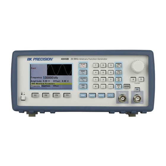
Generator. This section covers the instrument’s general description, specifications, and characteristics. 1.2 Description The 4045B is a versatile high performance function generators with arbitrary capabilities. Implemented using a DDS (direct digital synthesis) architecture, these instruments generate stable and precise sine, square, triangle and arbitrary waveforms. -
Page 13: Specifications
1.3 Specifications Model 4045B Frequency Characteristics Sine 0.01 Hz – 20 MHz Square 0.01 Hz – 20 MHz Triangle 0.01 Hz – 2 MHz Accuracy 0.001% (10 ppm) at < 500 Hz: 0.001% + 0.006 Hz Resolution 6 digits or 10 mHz... - Page 14 Square Rise/Fall < 20 ns (10% to 90% at full Time amplitude into 50 Ω) Variable Duty Square: 20% to 80 %, up to 2 Cycle/Symmetry Triangle: 1 % to 99 % in 1% steps, up to 200 kHz Symmetry Accuracy ±...
- Page 15 – 10 s) Modulation Characteristics Amplitude Modulation Internal 0.1 Hz – 20 kHz sine, square, or triangle waveform External for 100% modulation, 10 kΩ input impedance Frequency Modulation Internal 0.1 Hz – 20 kHz sine, square, or triangle waveform External for 100% modulation, 10 kΩ...
- Page 16 Accuracy ± 0.02 % ± 2 digits Sensitivity 25 mV typical General Memory Storage Store up to 20 instrument settings Arbitrary memory 1,000 points in flash memory Power Requirements 100 V – 240 V AC ± 10% (90 V – 264 VAC), 47 – 63 Hz Max.
- Page 17 To ensure the most current version of this manual, please download the latest version GlobalTestSupply www. .com Find Quality Products Online at: sales@GlobalTestSupply.com...
-
Page 18: Installation
Installation 2.1 Introduction This section contains installation information, power requirements, initial inspection and signal connections for the 4045B signal generator. 2.2 Package Contents Please inspect the instrument mechanically and electrically upon receiving it. Unpack all items from the shipping carton, and check for any obvious signs of physical damage that may have occurred during transportation. -
Page 19: Instrument Mounting
15 W of power dissipation. 2.4 Power Requirements The 4045B can be operated from any source of 90V to 264V AC, frequency from 48Hz to 66Hz. The maximum power consumption is 30VA. Use a slow blow fuse of 1A, UL/CSA approved as indicated on the rear panel of the instrument. -
Page 20: Fuse Replacement
2.5 Fuse Replacement There is a 1A, 250V rated slow blow fuse at the AC input. Should the fuse ever get blown, follow the steps below to replace: 1. Locate the fuse box next to the AC input connector in the rear panel. -
Page 21: Signal Connections
WARNING TO AVOID PERSONAL INJURY DUE TO SHOCK, THE THIRD WIRE EARTH GROUND MUST BE CONTINUOUS TO THE POWER OUTLET. BEFORE CONNECTION TO THE POWER OUTLET, EXAMINE ALL CABLES AND CONNECTIONS BETWEEN THE UNIT AND THE FACILITY POWER FOR A CONTINUOUS EARTH GROUND PATH. -
Page 22: Operating Instructions
Operating Instructions 3.1 General Description This section describes the displays, controls and connectors of the function generator. All controls for the instrument local operation are located on the front panel. GlobalTestSupply www. .com Find Quality Products Online at: sales@GlobalTestSupply.com... - Page 23 Power Button Power ON/OFF unit Displays all instrument data LCD Display and settings F1 – F4 function keys to Function Keys select menu options Select Sine, Ramp/Triangle, Waveform Buttons Square or Arbitrary waveform shape Enter numeric values for Numeric Keypad parameters Select unit of frequency, Units Keys...
-
Page 24: Display Window
3.2 Display Window The function generator has a color LCD display that can display up to 400 x 240 dots. When powering on the unit, sine waveform is selected and current settings will appear in the display. The bottom of the display shows a menu (selectable with function keys) that corresponds to the function, parameter, or mode display selected. -
Page 25: Output Connections
delivered from the function generator. Output Connector Use this connector to transfer the main output signal from the function generator. Trig In Connector Use this connector to apply an external trigger or gate signal, depending on the waveform generator setting, to the generator. - Page 26 Excessive distortion or aberrations caused by improper termination are less noticeable at lower frequencies, especially with sine and triangle waveforms. To ensure waveform integrity, follow these precautions: 1. Use good quality 50 Ω coaxial cable and connectors. 2. Make all connections tight and as short as possible.
-
Page 27: Menu Keys
3.6 MENU Keys These keys select the main menus for displaying or changing a parameter, function, or mode. 3.6.1 WAVEFORM Keys These keys select the waveform output and display the waveform parameter menu (frequency, amplitude and offset). Sine Menu GlobalTestSupply www. - Page 28 F1: Frequency – Selects and displays the frequency. Change the frequency setting using the cursor keys, rotary knob, or numerical keys. F2: Amplitude – Selects and displays the amplitude. Change the amplitude setting using the cursor keys, rotary knob, or numerical keys. F3: Offset –...
-
Page 29: Mode Key
Square Menu 3.6.2 MODE Key Selects the output mode: CONT (Continuous), TRIG (Triggered), GATE (Gated), and BRST (Burst). To select the output mode, press MODE, then press the function key that corresponds to the desired Mode menu option, as shown: GlobalTestSupply www. - Page 30 Mode Menu F1: Continuous – Selects continuous output. F2: Triggered – Triggers one output cycle of the selected waveform for each trigger event. F3: Gated – Triggers output cycles as long as the trigger source asserts the gate signal. F4: Burst – Triggers ‘N’ number of output cycles for each trigger event, where N ranges from 2 to 65,535.
- Page 31 Trigger Menu F1: Manual – Selects manual as the trigger source. To trigger the waveform generator, press this MANUAL trigger button again. F2: Internal – Selects the internal trigger generator as the trigger source. Change the internal trigger rate displayed with the rotary input knob.
-
Page 32: Utility Key
Burst Menu 3.6.3 UTILITY Key Utility Menu GlobalTestSupply www. .com Find Quality Products Online at: sales@GlobalTestSupply.com... - Page 33 F1: Recall – Recalls a previously stored front-panel setup from the selected buffer. Change the buffer number by using the rotary input knob. Valid storage buffer numbers are from 1 to 19 Buffer 0 is the factory default setup. F2: Store – Stores the current front-panel setup to the specified storage buffer.
-
Page 34: Sweep Key
Counter Screen Press F1 - Off to turn off the counter. 3.6.4 SWEEP Key Selects the Sweep Mode and allows entering of sweep parameters: Sweep Start, Sweep Stop, and Sweep Rate. To select the sweep mode, press SWEEP, then press the function key that corresponds to the desired Sweep menu option, as shown: GlobalTestSupply www. - Page 35 Sweep Menu F1: Off – Disables the sweep function. F2: Linear – Selects the Linear sweep shape. F3: Logarithmic – Selects the Logarithmic sweep shape. F4: Set – Defines the Sweep Start and Stop frequencies. GlobalTestSupply www. .com Find Quality Products Online at: sales@GlobalTestSupply.com...
-
Page 36: Modulation Key
Set Sweep Menu 3.6.5 MODULATION Key Selects the AM or FM Modulation mode. To select the output mode, press MODUL key, then press the function key that corresponds to the desired menu option, as shown: GlobalTestSupply www. .com Find Quality Products Online at: sales@GlobalTestSupply.com... - Page 37 Modulation Menu Press F2 to select AM menu: AM Menu GlobalTestSupply www. .com Find Quality Products Online at: sales@GlobalTestSupply.com...
- Page 38 F1: % - Defines the modulation depth (from 0 to 100%) F2: Frequency - Selects the modulation frequency, from 0.1 Hz to 20.00 kHz. F3: Shape - Selects the modulating waveform between Sine, Square, or Triangle. F4: External - Selects and enables the external modulation by an external signal applied to the Modulation In connector in the rear panel.
- Page 39 F1: Deviation - Defines the FM deviation frequency. F2: Frequency - Selects the modulation frequency, from 0.1 Hz to 20.00 kHz. F3: Shape - Selects the shape of the modulating waveform between Sine, Triangle, or Square. F4: External - Selects and enables the external modulation by an external signal applied to the Modulation In connector in the rear panel.
- Page 40 F1: Frequency Rate - (Frequency) Selects and displays the frequency. Change the frequency setting using the cursor keys, rotary knob or numerical keys. If a certain wavelength can't produce the waveform at the desired frequency, the waveform generator will display an “Out of Range”...
- Page 41 waveform generator will display a “Setting Conflict” error message. F4: Arb - Selects the Arbitrary waveform editing menu: Arbitrary Editing Menu F1: Start - Selects the arbitrary waveform start address. F2: Length - Selects the arbitrary waveform length. Use the START and LENGTH keys to mark a selection of the waveform memory that will be executed.
- Page 42 waveform, a message to save the Arbitrary wave will be displayed. Select YES or NO to save the new waveform. 3.6.7 Arbitrary EDIT Menu Enters data for creating arbitrary waveforms. You can enter data one point at a time, as a value at an address, draw a line from one point (a value at an address) to another point, create a predefined waveform, or combine...
- Page 43 Edit Menu F1: Point - This menu allows point-by- point waveform editing. When selected, the following menu is displayed: Point Menu GlobalTestSupply www. .com Find Quality Products Online at: sales@GlobalTestSupply.com...
- Page 44 F1: Adrs - Select the current address in the arbitrary waveform memory. F2: Data - Selects the data point value at the current address. You can change the point value from -2047 to 2047 F2: Line - This menu allows a line to be drawn between two selected points.
- Page 45 F1: From - Selects the starting point address. F2: To - Selects the ending point address. F3: Exec - Displays the Confirmation menu, F1:NO and F2:YES Confirmation Menu F3: Predef - (Predefined Waveforms) Selects one of the predefined waveforms: Sine, Triangle, Square and Noise.
- Page 46 Predefine Menu F1: Type - Use the rotary dial to select the waveform Sine, Triangle, Square or Noise. If Noise function is selected, a submenu is displayed to allow adding the noise to an available waveform or to generate it as a new noise waveform.
- Page 47 waveform (number of points for a full wave). Different waveforms have different limitations on the length, as shown in Table 3-1. Table 3-1: Waveform Length Limits for Predefined Waveforms Wave Minimum Divisible by Length Sine Triangle Square Noise F3: Scale - Selects the scale factor of the waveform.
-
Page 48: On Key
function menu options, ADD and NEW are available. Select ADD to add noise to an existing waveform, or NEW to create a new noise waveform. F4:Show - Displays the Arbitrary waveform on the full LCD display. Press any button to return to the MENU selection display. -
Page 49: Cursor Keys
3.8 Cursor Keys Use these keys to move the cursor (when visible) either left or right. They are used in conjunction with the rotary input knob to set the step size of the rotary input knob. 3.9 Rotary Input Knob Use this knob to increase and decrease numeric values. -
Page 50: Memory
assumes power-on default settings. Table 1 lists the factory default settings or selected after RECALL 0. Table 1 – Power-on Default Settings Key Function Value Description Function Sine Output Waveform Frequency 1.0000 kHz Waveform Frequency Amplitude 5.00 V Peak-to-peak output amplitude Offset 0.00 V... -
Page 51: Displaying Errors
3.12 Displaying Errors The waveform generator displays error messages when front-panel settings are either invalid or may produce unexpected results. Table 2 – Error Messages Message Description Text Out of range The set value is out of the instrument’s limits. Setting Settings conflict with another conflict... -
Page 52: Quick Start
3.13 Quick Start This section explains how to generate various waveforms and modify the output waveform. * Generating a waveform output * Modifying waveform output * Storing and recalling a waveform generator setup 3.13.1 Selecting a Standard Waveform You can select several standard waveforms as: sine, triangle, square. -
Page 53: Using Voltage Offset
3.13.3 Using Voltage Offset Through the offset parameter you can add a positive or negative DC level to the output waveform. To set voltage offset: 1. Select a waveform to display its menu. 2. Press F3:Offset to display the offset setting. 3. - Page 54 The function generator will overwrite and store settings into a buffer that had settings previously stored inside without a warning. Recalling Setups To recall stored front-panel setup: 1. Press UTILITY to display the menu. 2. Press F1:Recall to select the Recall mode. 3.
- Page 55 3.13.5 Creating an Arbitrary Waveform You can create an arbitrary waveform using the following methods: Enter individual data points Draw lines between data points Create a predefined waveform Combine any of these methods NOTE You can use the free downloadable software to create arbitrary waveforms.
- Page 56 memory, follow these steps: Press ARB main key to display the selection menu. Press F4 :ARB to display the arbitrary menu. Press F3:EDIT to display the Edit menu. Press F1:POINT, to select the point by point programming mode. Press F1:ADDRESS Use the rotary knob or the numerical keys to enter the address.
- Page 57 execution point rate is the execution time between each point in the waveform. The total time taken to run one period of the waveform is given by: number of points X rate Because the output frequency is a function of the rate and the number of points being executed, the formula ������������������...
- Page 58 3.13.8 Setting the Amplitude The following equation represents the relative output amplitude voltage relationship between the front-panel amplitude peak-to-peak setting and the data point values in waveform memory: ������������ �������������� ������������������ �� − �� �������������� �� �������� ���������� ���������� 4095 + ������������...
- Page 59 2. Press the ARB key and select the F4:ARB function. 3. Press F1:START to set the address. Valid entries range from 1 to 999. 4. Press F2:LENGTH to display the length of the waveform. 6. Use the rotary input knob or the numerical keys to enter the waveform length.
-
Page 60: Programming
Programming 4.1 Overview This section provides detailed information on programming the generator via the USB (virtual COM) interface. 4.1.1 Connecting to USB (Virtual COM) Interface Currently, the USB (virtual COM) interface supports Windows® XP/7 operating systems. To connect to a PC for remote communication, please follow the steps below: For Windows 7: 1. - Page 61 4. Click the “Close” button to stop the automatic search of the driver from Windows Update. 5. Now, go to Device Manager on the computer (Open up the “start” button, and right-click “Computer” and select “Properties”. Click “Device Manager” link on the top left of the side menu) 6.
- Page 62 7. In the following window, select “Browse my computer for driver software”, and following this, select “Let me pick from a list of device drivers on my computer”. 8. Now there will be a window listing Common hardware types. Click the “Next” button and select on the following screen “Have Disk…”...
- Page 63 12. The driver will now install. Once finished, under “Device Manager”, you should see under “Ports (COM & LPT)” an item labeled “BK Precision USB to Serial Converter (COM#)”. The “COM#” is the com port that can be used to access the virtual COM port for remote communication.
- Page 64 For Windows XP: 1. The USB driver is included in the CD that comes with the instrument. You can also go to and browse this product’s page to find and download the USB driver. 2. Connect the included USB Type A to Type B cable to the generator and the computer, then power on the instrument.
- Page 65 downloaded from the website labeled “atm6124_cdc.inf”. Select it and click “OK”. 9. The following screen will appear. 10. Click “Next”, and a prompt will appear: GlobalTestSupply www. .com Find Quality Products Online at: sales@GlobalTestSupply.com...
-
Page 66: Usb (Virtual Com) Settings
Computer”->Select “Properties”->Select “Hardware” tab- >Click “Device Manager”), you should see under “Ports (COM & LPT)” an item labeled “BK Precision USB to Serial Converter (COM#)”. The “COM#” is the com port that can be used to access the virtual COM port for remote communication. -
Page 67: Device States
BAUDRATE: 115200 PARITY: NONE DATA BITS: 8 STOP BIT: 1 FLOW CONTROL: NONE 4.2 Device States The device may be in one of the two possible states described below. 4.2.1 Local State (LOCS) In the LOCS state, the device may be operated from the front panel. -
Page 68: The Input Buffer
4.3.1 The Input Buffer The device has a 128-byte long cyclic input buffer. Decoding of remote messages is begun as soon as the input buffer is not empty, that is, as soon as the controller has sent at least one byte to the device. Should the input buffer be filled up by the controller faster than the device can remove the bytes and decode them, the bus handshake (CTS/RTS) is used to pause data transfer until... -
Page 69: Instrument Identification
4.4 Instrument Identification The *IDN? common query is used to read the instrument's identification string. The string returned is as follows: BK, MODEL 4045B,0,V0.1 The “V0.1” reflects the firmware version number and will change accordingly. 4.5 Instrument Reset The *RST common command effects an instrument reset to the factory default power up state. - Page 70 The Program Header represents the operation to be performed, and consists of ASCII character mnemonics. Two types of Program Headers are used in the MODEL 4045B: Instrument-control headers and Common Command and Query headers. Common Command and Query Program Headers consist of a single mnemonic prefixed by an asterisk ('*').
- Page 71 The Program Header Separator is used to separate the program header from the program data. It consists of one or more white space characters, denoted as <ws>. Typically, it is a space. c) Program Data The Program Data represent the values of the parameters being set, for example, the '1KHZ' in the above examples.
- Page 72 iii) NRf This is a decimal numeric data type, where NR1 indicates an integer number, NR2 indicates a fixed point real number, and NR3 indicates a floating point real number. iv) Numeric value program data This data type defines numeric values, as well as special cases of Character Data.
- Page 73 For example, to set the frequency to its maximum value we can send the command FREQ MAX Some Program Message Units either require, or can accept, more than one data element. Program data elements are separated from each other by the Program Data Separator.
-
Page 74: Status Reporting
will return the maximum value to which the frequency may currently be set. Not all Program Message units have query forms (for example, SAV), and some Program Message Units might have only the query form (for example IDN?). The instrument puts the response to the query into the output queue, from where it may be read by the controller. -
Page 75: Error Codes
The first error in the queue is returned, and the queue is advanced. 4.7.2 Error Codes The negative error codes are defined by SCPI. Positive codes are specific to the instrument. The error message is returned in the form <error number>,"<error description>" A table of error numbers and their descriptions is presented here. - Page 76 More parameters than allowed were received -109 Missing parameter Fewer parameters than necessary were received -110 Command header error -111 Header separator error -112 Program mnemonic too long The mnemonic must contain no more than 12 characters. -113 Undefined header -120 Numeric data error -121...
- Page 77 -178 Expression data not allowed Execution Errors An execution error indicates that the device could not execute a syntactically correct command, either since the data were out of the instrument's range, or due to a device condition. -200 Execution error An attempt was made to RECALL the contents of an uninitialized stored setting buffer.
- Page 78 The parameter value must be selected from a finite list of possibilities. Device-Specific Errors An error specific to the device occurred. -315 Configuration memory lost. Device memory has been lost. -330 Self-test failed. -350 Queue overflow. Error codes have been lost due to more than 10 errors being reported without being read.
- Page 79 -410 Query INTERRUPTED. Data were sent before the entire response of a previous query was read. -420 Query UNTERMINATED. An attempt was made to read a response before the complete program message meant to generate that response was sent. Warnings The execution of some commands might cause an undesirable instrument state.
-
Page 80: Common Commands
Version number Command Type: Common Query Syntax: *IDN? Response: BK, MODEL 4045B,0,V1.1 4.8.2 Internal Operation Commands *RST - Reset command The Reset command performs a device reset. It causes the device to return to the factory default power up state. Type:... -
Page 81: Device Trigger Commands
This command is used to restore the state of the device to that stored in the specified memory location. Arguments Type <NRf> Range 0 to 19 (4045B). Non integer values are rounded before execution Type: Common Command Syntax: *RCL<ws><NRf> Example:... -
Page 82: Instrument Control Commands
*SAV - Save instrument state This command is used to store the current instrument state in the specified memory location. Arguments Type: <NRf> Range: 0 to 9. Non integer values are rounded before execution Type: Common Command Syntax: *SAV<ws><NRf> Example: *SAV 2 Stored setting location 0 stores the factory defaults, and is a read-only location. -
Page 83: Default Subsystem
specifications. The '<ws>' is used to denote a white space character. Note: When controlling the instrument remotely, do not interrupt the instrument with front panel interactions. Although the instrument will be automatically changed back to LOCS (local) mode, subsequent remote commands may cause errors during communication, in which will require a need of restarting the instrument before continuing again with remote operations. - Page 84 SWRAte <numeric value> SWSTArt <numeric value> SWSTOp <numeric value> MODE CONT/ TRIG / GATE / BRST TRIG INT / EXT TRAte <numeric value> BURSt <numeric value> FREQuency <frequency> The frequency command controls the frequency of the output waveform. Arguments Type: Numeric.
- Page 85 FREQ 5E3 FREQ MAXIMUM FREQ MIN Query Syntax: FREQuency?[<ws>MAXimum|MINimum] Examples: FREQ? FREQ? MAX Response: Considerations: 1) The MIN and MAX arguments refer to currently settable minimum or maximum. 2) FIXed is alias for CW. Point Rate RATE <point rate> This command is used to set the point rate. It is coupled with the frequency of the waveform by the relation: Frequency = 1/(Point Rate * Wavelength)
- Page 86 Rounding: to 4 digits Command Type: Setting or Query Setting Syntax: RATE<ws><point rate>[units] RATE<ws>MINimum|MAXimum Examples: RATE 100NS Query Syntax: RATe?[<ws>MINimum|MAXimum] Response: Note: You can alternately use the :ARB:PRATe command. AMPLitude <p-p amplitude> The amplitude command is used to set the peak-to-peak amplitude of the output waveform.
- Page 87 AMPL 2.5V AMPL MAX Query Syntax: AMPLitude? <ws>MINimum|MAXimum] Examples: AMPL? AMPL? MAX Response: Considerations: 1) The MAXimum amplitude is dependent on the offset. 2) The MAX and MIN arguments should not be used in a program message containing an OFFSet command, since these values are evaluated during parsing, based on the current value of the offset.
- Page 88 OFFSet<ws>MINimum|MAXimum Examples: OFFS 2.5 OFFS 2.5V OFFS MAX Query Syntax: OFFSet?[<ws>MINimum|MAXimum] Examples: OFFS? OFFS? MAX Response: Considerations: 1) The MAXimum offset is dependent on the amplitude. 2) The MAX and MIN arguments should not be used in a program message containing an AMPLitude command, since these values are evaluated during parsing, based on the current value of the amplitude.
- Page 89 DCYCle <duty cycle value> This command is used to set the duty-cycle of the square wave or the symmetry of triangular wave. The value is given in percent . Arguments Type: Numeric Units: None (percent implied) Range: 1 to 99 Rounding: To integer Command Type:...
- Page 90 MODULation This command activates or deactivates modulation: Command Type: Setting or Query Setting Syntax: MODULation OFF|AM|FM|INT|EXT Examples: MODULation FM MODULation OFF MODULation EXT Query Syntax: MODULation? Response: AM INT AM EXT | FM INT FM EXT DEPTh This command sets the AM modulation depth in % Arguments Type: Numeric...
- Page 91 Examples: DEPTh 50 Query Syntax: DEPTh?[<ws>MINimum|MAXimum] Response: MODFRequency This command sets the AM and FM modulating waveform frequency Arguments Type: Numeric. Units: MHz, KHz, Hz (default) Range: Fmax = 20 KHz Fmin = 0.01 Hz Command Type: Setting or Query Setting Syntax: MODFR<ws><frequency>[units]...
- Page 92 MODSHape This command selects the modulating waveform shape Arguments Type: Character Options: SINusoid, TRIangle, SQUare Command Type: Setting or Query Setting Syntax: MODSHape<ws><SIN|TRI|SQU> Examples: MODSHape SIN MODSHape TRI Query Syntax: MODSHape? Response: SIN|TRI|SQU DEViation This command sets the FM modulation deviation Arguments Type: Numeric.
- Page 93 DEV 5E3 DEV MAXIMUM DEV MIN Query Syntax: DEViation?[<ws>MAXimum|MINimum] Examples: DEV? DEV? MAX Response: SWEep This command activates or deactivates sweep: Arguments Type: Boolean Command Type: Setting or Query Setting Syntax: SWE<ws>ON|OFF|LIN|LOG Examples: SWE ON SWE LIN Query Syntax: SWE? Response: OFF|LIN ON|LIN OFF|LOG ON|LOG Note: Sweep will automatically be active if set to Linear or...
- Page 94 SWRAte This command sets the time for one complete sweep: Arguments Type: Numeric Units: S, mS, uS, nS Range: 10mS to 100S Command Type: Setting or Query Setting Syntax: SWRAte<ws><time>[units] SWRAte<ws>MINimum|MAXimum Examples: SWRAte 50MS Query Syntax: SWRAte?[<ws>MINimum|MAXimum] Response: SWSTArt This command sets the start frequency of the sweep: Arguments Type: Numeric.
- Page 95 SWSTArt 5E3 SWSTArt MAXIMUM SWSTArt MIN Query Syntax: SWSTArt?[<ws>MAXimum|MINimum] Examples: SWSTArt ? SWSTArt ? MAX Response: SWSTOp This command sets the stop frequency of the sweep: Arguments Type: Numeric. Units: MHz, KHz, Hz (default) Range: Dependent on the frequency range of the current function.
- Page 96 MODE <trigger mode> This command is used to set the trigger mode. Arguments Type: Character Options: CONTinuous TRIGger GATE BURSt Command Type: Setting or Query Setting Syntax: MODE<ws><CONT|TRIG|GATE|BURS> Examples: MODE CONT MODE BURS Query Syntax: MODE? Response: CONT|TRIG|GATE|BURS TRIGger <trigger source> This command is used to select the trigger source, for use in the Trigger, Gate and Burst trigger modes.
- Page 97 Setting Syntax: TRIGger<ws><INT|EXT> Examples: TRIG EXT TRIG INT Query Syntax: TRIGger? Response: INT|EXT BURSt <burst count> This command is used to set the number of cycles to be output in the BURST mode. It is not a standard SCPI command. Arguments Type: Numeric...
- Page 98 TRAte <trigger rate> Sets the rate of the internal trigger. Arguments Type: Numeric Units: S, mS, uS, nS Range: 1 uS to 10S Rounding: to 4 digits Command Type: Setting or Query Setting Syntax: TRAte<ws><value>[units] TRAte<ws>MINimum|MAXimum Examples: TRAte 10E-6 TRAte MIN Query Syntax: TRAte?[<ws>MINimum|MAXimum]...
-
Page 99: Arbitrary Subsystem
Query Syntax: ERRor? Response: <Error number>, "<error description>" 4.9.2 Arbitrary Subsystem The Arbitrary subsystem is not part of the SCPI standard. It was developed to suit the needs of the instrument. Within this subsystem are found commands to: 1) control the point rate, start address, wavelength, and synchronization pulse address;... - Page 100 :STARt <numeric value> :LENGth <numeric value> :SAVe Point Rate ARBitrary:PRATe <point rate> This command is used to set the point rate. It is coupled with the frequency of the waveform by the relation: Frequency = 1/(Point Rate * Wavelength) Thus changing the point rate will result in a change in frequency.
- Page 101 Address :ARBitrary:ADDRess <address> This command sets the current address of the waveform. It is used to determine to where arbitrary data are to be written. Arguments Type: Numeric Range: 1 to 1,000 Rounding: to integer value Command Type: Setting or Query Setting Syntax: :ARBitrary:ADDRess<ws><address>...
- Page 102 Type: Numeric. Definite form arbitrary block. Indefinite form arbitrary block Numeric Range: -2047 to 2047 ASCII Rounding: to integer value Command Type: Setting or Query Setting Syntax Numeric: :ARBitrary:DATA<ws><numeric>{[,<numeric]} Example :ARB:DATA 100,200,1000,2000,- 2000 Query Syntax: :ARBitrary:DATA?<ws><number of points>,ASCii Response: Data are returned in the decimal numeric form.
- Page 103 Considerations: 1) The value of the data at the start and end points must first be set by the user, using the :ARB:DATA command. 2) The range of the straight line cannot overlap with protected memory. 3) The end address must be greater than the start address.
- Page 104 Range SIN: 16 to 1000; divisible by 4 SQU: 2 to 1000; divisible by 2 TRI: 16 to 1000; divisible by 4 NOIS: 16 to 1000, ANO: 16 to 1000, Rounding: to integer value. Scale Type: Numeric. MIN sets the scale to 1; MAX sets the scale to 100 Range: 1 to 100 (See considerations)
- Page 105 NOIS Start Address :ARBitrary:STARt <start address> This command sets the start address of the waveform to be run. Arguments Type: Numeric Range: 1 to 999 Rounding: to integer value Command Type: Setting or Query Setting Syntax: :ARBitrary:STARt<ws><start address> :ARBitrary:STARt<ws>MINimum|MAXimum Example: :ARB:STAR 100 Query Syntax:...
- Page 106 This command sets the length of the waveform being run. Arguments Type: Numeric Range: 2 to 1000 Rounding: to integer value Command Type: Setting or Query Setting Syntax: :ARBitrary:LENGth<ws><length> :ARBitrary:LENGth<ws>MINimum|MAXimum Example: :ARB:LENG 1E3 Query Syntax: :ARBitrary:LENGth?[<ws>MINimum|MAXimum] Example: :ARB:LENG? Response: Considerations: 1) Changing the wavelength will change either the frequency.
- Page 107 SERVICE INFORMATION Warranty Service: Please go the support and service section on our website to obtain a RMA #. Return the product in the original packaging with proof of purchase to the address below. Clearly state on the RMA the performance problem and return any leads, probes, connectors and accessories that you are using with the device.
- Page 108 LIMITED THREE-YEAR WARRANTY B&K Precision Corp. warrants to the original purchaser that its products and the component parts thereof, will be free from defects in workmanship and materials for a period of three years from date of purchase. B&K Precision Corp. will, without charge, repair or replace, at its option, defective product or component parts.
- Page 109 Index Amplitude, 13, 28, 50 Linear, 35 cursor, 49 Offset, 28 duty cycle, 28 recall, 54 Errors, 51 safety, 3 factory default, 50 Specifications, 13 frequency, 28 store, 53 Impedance Matching, Symmetry, 28 Sync Out, 25 LCD, 24 GlobalTestSupply www. .com Find Quality Products Online at: sales@GlobalTestSupply.com...
- Page 110 © 2012 B&K Precision Corp. V022014 GlobalTestSupply www. .com Find Quality Products Online at: sales@GlobalTestSupply.com...
Need help?
Do you have a question about the 4045B and is the answer not in the manual?
Questions and answers