Table of Contents
Advertisement
Advertisement
Table of Contents

Related Manuals for BK Precision 880


Summary of Contents for BK Precision 880
- Page 1 Model Dual Display LCR METER INSTRUCTION MANUAL...
-
Page 3: Safety Summary
Safety Summary Before applying power to this instrument: Read and understand the safety and operational information in this manual. Apply all the listed safety precautions. Verify that the voltage selector at the line power cord input is set to the correct line voltage. - Page 4 You must ensure that each accessory you use with this instrument has a category rating equal to or higher than the instrument's category rating to maintain the instrument's category rating. Failure to do so will lower the category rating of the measuring system. Electrical Power This instrument is intended to be powered from a CATEGORY II mains power environment.
- Page 5 In the presence of noxious, corrosive, or flammable fumes, gases, vapors, chemicals, or finely-divided particulates. In relative humidity conditions outside the instrument's specifications. In environments where there is a danger of any liquid being spilled on the instrument or where any liquid can condense on the instrument.
- Page 6 Do not clean the instrument, its switches, or its terminals with contact cleaners, abrasives, lubricants, solvents, acids/bases, or other such chemicals. Clean the instrument only with a clean dry lint-free cloth or as instructed in this manual. Not for critical applications This instrument is not authorized for use in contact with the human body or for use as a component in a life-support device or system.
- Page 7 the fuse types, voltage ratings, and current ratings specified in this manual or on the back of the instrument. Failure to do so may damage the instrument, lead to a safety hazard, or cause a fire. Failure to use the specified fuses will void the warranty. The replacement of current-measurement mode protection fuses in multimeters is especially important.
- Page 8 Measurement of DC resistance in circuits that contain small DC biases (for example, thermoelectric voltages) can produce incorrect results. To minimize the effect of such biases, measure the DC resistance with normal and reversed test lead polarity and algebraically average the results, even if one of the measurements results in a negative resistance. Shipment It is recommended that you retain the original packing that the instrument was shipped in.
-
Page 9: Safety Guidelines
Safety Guidelines To ensure that you use this device safely, follow the safety guidelines listed below: This meter is for indoor use, altitude up to 2,000 m. The warnings and precautions should be read and well understood before the instrument is used. -
Page 10: Safety Symbols
Safety Symbols Refer to the user manual for warning information to avoid hazard or personal injury and prevent damage to instrument. Electric Shock hazard Alternating current (AC) Chassis (earth ground) symbol. Ground terminal DC Current Indicates inside pin is positive (+), outside is negative (-) CAUTION indicates a hazardous situation which, if not avoided, will... -
Page 11: Compliance Statements
Compliance Statements Disposal of Old Electrical & Electronic Equipment (Applicable in the European Union and other European countries with separate collection systems) This product is subject to Directive 2002/96/EC of the European Parliament and the Council of the European Union on waste electrical and electronic equipment (WEEE), and in jurisdictions adopting that Directive, is marked as... -
Page 12: Table Of Contents
TABLE OF CONTENTS Safety Summary ............................. 1 Safety Guidelines ..............................7 Safety Symbols ................................. 8 Compliance Statements ............................9 TABLE OF CONTENTS ........................10 INTRODUCTION ............................ 13 PACKAGE CONTENTS ............................13 FRONT PANEL OVERVIEW ......................... 14 Front Panel Display Descriptions ..........................14 Front Panel Buttons .............................. - Page 13 Measurement Rate (RATE) ............................. 28 Parallel and Series Measurement Mode ......................... 29 Default Settings ..................................29 Selecting Measurement Mode..............................29 Tolerance (TOL) ..............................29 Tolerance Range ..................................29 Setup Tolerance Mode ................................30 Disable Tolerance Mode ................................. 31 Utility Menu (UTIL) ..............................31 Entering Utility Menu ................................
- Page 14 Capacitance .................................... 56 Inductance ....................................56 Resistance ....................................56 Guard Terminal ............................... 56 SPECIFICATIONS ..........................57 General Specifications ............................57 Accuracy Specifications ............................58 Testing Conditions: ................................. 58 Capacitance(C) and Dissipation (D) ............................61 ( ) ( θ ) Impedance and Phase Angle ..........................
-
Page 15: Introduction
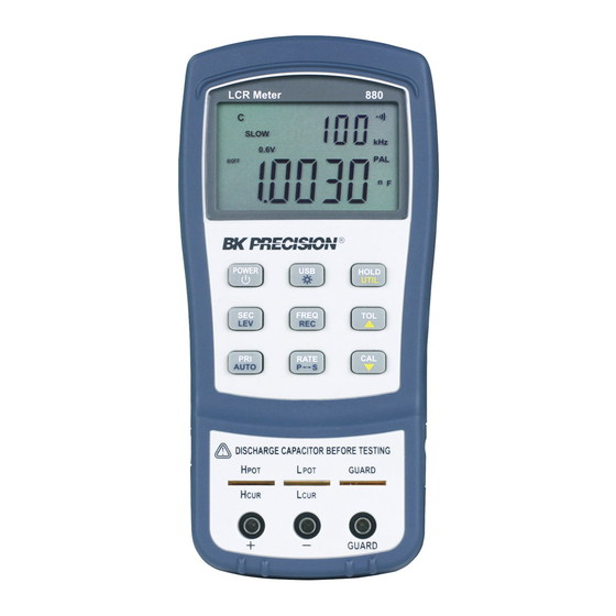
INTRODUCTION B&K Precision’s 880 handheld LCR meter is designed for measuring the inductance, capacitance and resistance of components. This LCR meter provides a 40,000-count primary parameter reading and a secondary parameter reading with a resolution of 0.0001 with an accuracy of up to 0.1%. -
Page 16: Front Panel Overview
FRONT PANEL OVERVIEW Figure 1 - Front Panel Display Front Panel Display Descriptions 1. LCD display 2. USB communication / *Back light button 3. Power ON/OFF button 4. Frequency and record mode selection 5. Secondary display mode (D/Q//ESR, etc.)/ Test Level 6. -
Page 17: Front Panel Buttons
Note: Use with included power adapter only. Use with improper power adapters may damage the instrument. Use power adapter only when there is a rechargeable battery inserted or when there is no battery. *WARNING: Before connecting an external power adapter, please check the battery compartment in the rear side of the unit. -
Page 18: Lcd Display Overview
LCD DISPLAY OVERVIEW Figure 2 - LCD Display LCD Display Descriptions 1. MAX – Maximum reading indicator in the record mode 2. LDCRZ – Primary parameters display 3. AVG – Average reading indicator in the record mode 4. MIN – Minimum reading indicator in the record mode 5. -
Page 19: Special Display Indicators
– Low battery/charging indicator 27. @OFF –Auto power-off indicator 28. 1V 0.6V 0.3V- Display test level 29. TOL –Tolerance mode indicator 30. FAST- Fast/Slow measuring rate indicator Special Display Indicators Indicates short connectors Indicates open connectors Error indication Indicates calibration mode Indicates damaged or open fuse AD converter error AD converter error... -
Page 20: Test Port
Test Port The 880 is designed with two test ports: the 3-terminal port for convenience and a 5-terminal port for higher accuracy. 5-terminal test slot 3-terminal test port High Potential Low Potential Protect Potential Figure 3 - Test Ports The standard banana plugs allow the connection of banana to alligator test lead. This configuration has lower testing accuracy when compared to the 5-terminal test port. -
Page 21: Powering Instrument
There are two methods to power the instrument: Battery and external source. Installing Battery The 880 LCR meters can use a battery to provide power to the instrument so that it can be portable. The meters use a standard 9V size battery (or NEDA 1604, JIS006P, IEC6F22 carbon-zinc or alkaline battery) or a rechargeable Ni-MH battery. -
Page 22: Connecting External Power Source
2 seconds to turn on the instrument. Connecting External Power Source The 880 can also be powered using an external AC adapter. The model 880 comes with this adapter included in the package. Note: For external power, use AC adapter rated for output 12VDC, 150mA, center pin positive 4mm connector only. -
Page 23: Low Battery Indication
See “Installing Battery” for instructions. Backlit Display Model 880 LCR meter has a backlit display that allows you to see the LCD display in dark conditions. To turn on the back light, press and hold down button for 2 seconds. -
Page 24: When Using External Power
Single charge cycle is about 160 minutes and charge current is approximate 120mA. If a battery is fully charged, then the 880 will stop charging the battery. WARNING: DO NOT connect to external power when a non-rechargeable battery is installed. -
Page 25: Operation Instructions
OPERATION INSTRUCTIONS WARNING: If the component to be measured is a capacitor, be sure that the capacitor is fully discharged BEFORE inserting it into the input sockets or terminals. For large capacitors, it may take longer periods of time for a full discharge. Inserting a charged or partially charged capacitor into the meter’s input sockets or terminals may produce an electric hazard and may also damage the instrument, making it unusable. -
Page 26: Calibration (Cal)
Recording State This is the default mode when static recording is enabled. In this mode, LCD will display “MAX AVG MIN” indicator. In a relatively stable range of test data, a beep tone will sound once a recording has been stored. NOTE: When the data fluctuation range is higher than 1%, data record will dynamically be refreshed. -
Page 27: Enter Cal Mode
There are two functions under CAL Mode: Open Cal will reduce the effects of contact resistors and test leads. Short Cal will minimize the influence of distributed capacitors and resistors on testing high impedance elements. Enter CAL Mode For convenience, OPEN CAL and SHORT CAL are designed to share a button. -
Page 28: Primary Parameter (Pri)
Figure 8 - Short Calibration Notes: 1. If test frequency is changed, calibration should be done again before making precision measurements. Once calibration is done on a selected test frequency, calibration data will remain until power off. 2. Either open or short calibration is not associated with measurement function, therefore changing the test function does not require re-calibration. -
Page 29: Secondary Parameter (Sec)
Secondary Parameter (SEC) The secondary display of the LCR meter is used to display measured values of four parameters, which provide additional information about the component being tested. These parameters are: D (Dissipation factor), Q (Quality factor), θ (Phase angle), and ESR (Equivalent series resistance). -
Page 30: Disable Auto Lcr Mode
“AUTO” indicator on LCD will disappear when auto LCR mode is turned off. Test Frequency (FREQ) The 880 LCR meter uses an AC signal to test and measure components at the input sockets or terminals. With this measurement method, a test frequency must be selected. The test frequency can affect the accuracy of the results depending on what frequency is selected, and what type and value of component is being measured or tested. -
Page 31: Parallel And Series Measurement Mode
Parallel and Series Measurement Mode The LCR meter offers the option to select between parallel or series measurement modes. Depending on which mode is selected, the method used to measure the component will be different. Additionally, one measurement mode may provide better accuracies over the other measurement mode depending on the type of component and the value of the component to be tested. -
Page 32: Setup Tolerance Mode
Setup Tolerance Mode 1. Select the primary measurement mode based on the type of components to be measured. This is done by pressing the button to configure the desired measurement mode. Note: Be sure to select the correct measurement mode, as tolerance mode cannot be activated unless the correct mode is selected. -
Page 33: Disable Tolerance Mode
6. To select the tolerance range, press the button once more. For each button press, the meter will cycle through the tolerance range percentage in this order: 1%, 5%, 10%, 20% which will also be indicated on the LCD. The component to be tested will be verified with the tolerance within the selected % of the “standard”... - Page 34 Menu Options Settings/Parameters dCdly DCR trigger delay bEEP ON / OFF AoFF 5 / 15 / 30 / 60 / OFF PrE / Set yES / NO bAtt Battery Voltage Table 2 - Utility Menu Options and Settings The 6 menu options allow users to control or check the following options: ...
- Page 35 Using the arrow keys to add or minus the time by 1. Long time pressing arrow keys can move the current cursor to left or right. The setup is promptly effective once modified. NOTE: when the setting is not 0000, the higher the setting time, the DCR measurement speed becomes more slowly.
- Page 36 SECONDARY REPRESENTATION DISPLAY 5 minutes 15 minutes 30 minutes 60 minutes No timer. Manual power off only Table 3 - Auto Power-Off Options Default Setting: 5 mins When the auto power-off option is set to any of the configured settings in Table 3 above (Error! Reference source not found.except for “OFF”), upon exiting the utility menu the LCD display will have a “@OFF”...
- Page 37 Auto LCR Tolerance mode state Reference value for Tolerance mode Configure and Save Power-up State Follow the below procedure to setup and store a power-up state into internal memory. 1. Before entering into the utility menu, configure all the settings and parameters desired for power up state.
-
Page 38: Exit Utility Menu
Default Setting: No To reset the meter to default settings, first select the “dEF” menu option by using the use button to browse through the utility menu. When the primary display shows “dEF”, either press button to change the setting so that the secondary display shows “yES”. Upon saving and exiting the utility menu, the instrument will automatically reset back to its original settings. -
Page 39: Usb
Saving and Exiting To save all utility menu option settings and to exit the menu, press and hold down the button for 2 seconds. After this, the meter will exit the menu, and all settings will be saved. Exiting without Saving If user decides to exit the utility menu without making any changes or saving any changes to “PuP”... - Page 40 the meter, remove external AC adapter if used and/or remove the battery from the battery compartment. Refrain from further operation until the fuse is replaced. Please contact B&K Precision for assistance.
-
Page 41: Quick Start Guide
QUICK START GUIDE Do not measure a capacitor that is not fully discharged. Connecting a charged or partially charged capacitor to the input terminals will damage the instrument. When measuring within a circuit, the circuit must be de-energized before connecting the test leads. - Page 42 Figure 11 - Inductance Measurement Setup...
-
Page 43: Capacitance Measurement
Capacitance Measurement Fully discharge capacitor BEFORE inserting it into the instrument. Failure to do this may result in damage to the meter and may cause electrical hazards. 1. Press button for one second to turn on the meter. 2. Press button until “C”... -
Page 44: Ac Resistance Measurement
AC Resistance Measurement 1. Press down button for one second to turn on the meter. 2. Press button until “R” is on the screen to select resistance measurement. 3. Insert resistor or resistive component into the input sockets or connect alligator leads into the banana jack input terminals and connect the clips to the component leads as illustrated in Figure 13 –... -
Page 45: Direct Current Resistance (Dcr) Measurement
Direct Current Resistance (DCR) Measurement 1. Press the button for 2 seconds to turn the instrument on. button until “DCR” is displayed on the screen to select direct current 2. Press the resistance measurement. 3. Insert impedance (resistor, capacitor or inductor) into test slots or connect tested impedance through a proper test accessory (i.e., banana plug-crocodile clip test leads, test fixture or SMD test tweezers). -
Page 46: Impedance Measurement
Impedance Measurement 1. Press button for one second to turn on the meter. 2. Press button until “Z” is on the screen to select impedance measurement. 3. Insert component into the input sockets or connect alligator leads into the banana jack input terminals and connect the clips to the component leads as illustrated in Figure 15 - Impedance Measurement Setup 4. -
Page 47: Remote Communication
REMOTE COMMUNICATION The meter has the capability to communicate with a PC over the mini USB interface. Upon installation of a USB driver, the PC can control the instrument over virtual COM (RS-232). The mini USB communication interface of the meter is designed in full duplex and has a 64-byte input and output buffer, making it reliable and efficient for data transmission. -
Page 48: Usb (Virtual Com) Configuration
The USB will be recognized as a virtual COM on the PC, thus serial port settings must be configured properly for remote communication to be successful. Find the settings used by the 880 meter below: Baudrate: 9600 Data bits: 8 ... -
Page 49: Command Protocols
Note: Alternatively, auto fetching mode can be disabled when a remote command is sent to the instrument, turning it back into remote mode. In this event, the RMT indicator will appear on the LCD display, and auto fetching will be disabled automatically. To re-enabled auto fetching again in this state, first press the button once to exit out of remote mode and return to local mode. -
Page 50: Responding Message
Responding Message Returned result After the meter executes a query command, the return of the result will be in the following format: <Result> + <CR> <LF> For example, in auto fetching mode, the meter will send the measured data automatically when the measurement cycle is completed. -
Page 51: Command Reference
Command Reference *IDN? Query instrument ID. Return: <instrument model>, <firmware version>, <serial number> *LLO Local Lockout. This means that all front panel buttons, including the RMT key is not available. (POWER button is enabled.) *GTL Go to local and remove local lockout. If *LLO is sent, the only way to operate front panel is to go to *GTL. - Page 52 VOLTage subsystem VOLTage <value> Description:set the test level (only effective in L,C,R,Z) Parameters are 0.3, 0.6, 1 or 3e-1,6e-1,1e0 Example: VOLTage 0.3 Set the test level to 0.3 V VOLTage? Description: set the current test level Return:<0.3V|0.6V|1V> FUNCtion subsystem FUNCtion:impa < L | C | R | Z | DCR > Description: Select the primary parameter Example: FUNCtion:impa L Selects L as the primary parameter...
- Page 53 CALCulate subsystem CALCulate:TOLerance:STATe < ON | OFF > Description: Enable or disable tolerance mode Example: CALCulate: TOLerance:STATe ON CALCulate:TOLerance:STATe? Description: Query the tolerance mode Return: <ON, OFF > CALCulate:TOLerance:NOMinal? Description: Query the nominal value Return: NR3 or -----(exceeding data range) CALCulate:TOLerance:VALUe? Description: Query the percentage value of tolerance Return: NR3 or ----- (exceeding data range)
- Page 54 CALCulate:RECording:AVERage? Description: Query the average value of recording function Return: <NR3, NR3> ( primary and secondary parameters, when data exceeds limits or there is no data, what returns is“----”.) CALCulate:RECording:PRESent? Description: Query the present value of recording function Return: <NR3, NR3> ( primary and secondary parameters, when data exceeds limits or there is no data, what returns is“----”.) FETCh Subsystem FETCh?
- Page 55 Summary of Supported SCPI Commands Command Parameter Function FREQuency <Value> Set the Test Frequency FREQuency? Query the Test Frequency VOLTage <Value> Set the Test level VOLTage? Query the Test level FUNCtion :impa <Literal> Select the primary display parameter :impa? Query the primary display parameter :impb <Literal>...
-
Page 56: Error Codes
Error Codes If codes or parameters, originated from bus and transmitted to the meter, are fault, the meter will terminate the analysis and execution codes. At the same time, error code will be displayed on LCD and beep will be sound. Below defines the error description based on the error code. -
Page 57: Selecting Series Or Parallel Mode
be measured at higher frequencies such as 1 kHz or 10 kHz. However, a 120 Hz test signal is used to measure inductors that are used for applications such as filter chokes in power supplies, in which are typically operated at 60 Hz AC (in U.S.) with 120 Hz filter frequencies. In general, inductors below 2 mH should be measured at 1 kHz frequency while inductors above 200 H should be measured at 120 Hz. -
Page 58: Capacitance
Some inductors are intended to operate at a certain DC bias to achieve a certain inductance value. However, the 880 LCR meter cannot produce such biasing scheme and external biasing should not be attempted because external power would be applied to the instrument and cause serious damage to the meter. -
Page 59: Specifications
SPECIFICATIONS Below are some remarks in regards to all specifications pertaining to the 880 LCR meter. *Specifications are subject to change without notice. Notes: 1. Measurement performed at the test socket. 2. Measurements performed after correct open and short calibration. -
Page 60: Accuracy Specifications
Charge Time and Current Max.: 160min. Max. Current: 100mA (typical) Operating Current (with Max.:35mA backlight off) Typical:25mA (@1kHz, 0.6 Vrms,100Ω load) Standby Current (Power Max. :11μA (typical) Off) Power Requirements 1) DC 9V Battery 2)Ext. AC Adapter: DC 12 Vmin –15 Vmax. (Load 50 mA Min.) Operation Condition Temperature... - Page 61 Inductance (L) and Quality Factor (Q) Accuracy Recommended Range Display Range Equivalent Mode De * 1000H 400.0H1000.0H 1%+3 digits 1.00%+3 digits Parallel 400H 40.00H399.99H 0.35%+2 digits 0.35%+2 digits Parallel 4.000H39.999H 0.1%+2 digits 0.1%+2 digits Parallel 400.0mH3.9999H 0.1%+2 digits 0.1%+2 digits ---- 400mH 40.00mH399.99mH...
- Page 62 Quality factor Q and Accuracy Qe is calculated by the following formula: ≤ 1, is the measurement value.
-
Page 63: Capacitance(C) And Dissipation (D)
Capacitance(C) and Dissipation (D) Recommended Accuracy Display Range Range Equivalent Mode 20mF 4.000mF20.000mF 5%+5 digits 5%+5 digits Series 400.0μF3.9999mF 1%+3 digits 1%+3 digits Series 400μF 40.00μF399.99μF 0.35%+2 digits 0.35%+2 digits Series 40μF 4.000μF39.999μF 0.1%+2 digits 0.1%+2 digits Series 4μF 400.0nF3.9999μF 0.1%+2 digits 0.1%+2 digits ----... -
Page 64: Impedance And Phase Angle
( ) ( ) Impedance and Phase Angle θ Accuracy Recommended Range Display Range e Equivalent Mode 1.75 10M 4.000M10.000M 3%+5 digits Parallel 0.75 4M 400.0k3.9999M 1%+3 digits Parallel 0.25 400k 40.00k399.99k 0.35%+2 digits Parallel 0.1 40k 4.000k39.999k 0.1%+2 digits Parallel 0.1... - Page 65 Equivalent Series Resistance Accuracy of equivalent series resistance is calculated according to the below formula: Rse = : Actual impedance, φe is the phase angle accuracy, Notice: The accuracies of ESR and Rs are same. Equivalent Parallel Resistance Accuracy of equivalent series resistance is calculated according to the below formula: ...
-
Page 66: Maintenance
MAINTENANCE Do not perform any service by yourself. Service should only be done by qualified personnel and trained technicians. Service If the instrument fails to operate, check battery and test leads. Replace them as necessary. If the instrument still cannot work, verify with the operating instructions to make sure correct procedures are followed. -
Page 67: Service Information
SERVICE INFORMATION Warranty Service: Please go the support and service section on our website www.bkprecision.com to obtain a RMA #. Return the product in the original packaging with proof of purchase to the address below. Clearly state on the RMA the performance problem and return any leads, probes, connectors and accessories that you are using with the device. -
Page 68: Limited Warranty
LIMITED WARRANTY B&K Precision Corp. warrants to the original purchaser that its products and the component parts thereof, will be free from defects in workmanship and materials for a period of three years from date of purchase. B&K Precision Corp. will, without charge, repair or replace, at its option, defective product or component parts. - Page 69 (Page intentionally left blank)
- Page 70 (Page intentionally left blank)
- Page 71 22820 Savi Ranch Parkway Yorba Linda, CA 92887 www.bkprecision.com © 2016 B&K Precision Corp. Printed in China v052716...
Need help?
Do you have a question about the 880 and is the answer not in the manual?
Questions and answers