Sign In
Upload
Download
Table of Contents
Contents
Add to my manuals
Delete from my manuals
Share
URL of this page:
HTML Link:
Bookmark this page
Add
Manual will be automatically added to "My Manuals"
Print this page
×
Bookmark added
×
Added to my manuals
Manuals
Brands
BK Precision Manuals
Measuring Instruments
894
User manual
BK Precision 894 User Manual
500 khz/1 mhz lcr meter
Hide thumbs
1
2
3
4
5
6
7
8
9
Table Of Contents
10
11
12
13
14
15
16
17
18
19
20
21
22
23
24
25
26
27
28
29
30
31
32
33
34
35
36
37
38
39
40
41
42
43
44
45
46
47
48
49
50
51
52
53
54
55
56
57
58
59
60
61
62
63
64
65
66
67
68
69
70
71
72
73
74
75
76
77
78
79
80
81
82
83
84
85
86
87
88
89
90
91
92
93
94
95
96
97
98
99
100
101
102
103
104
105
106
107
108
109
110
111
112
page
of
112
Go
/
112
Contents
Table of Contents
Bookmarks
Table of Contents
Table of Contents
Product Overview
Package Contents
Dimensions
Front Panel Overview
Front Panel Description
Rear Panel Overview
Rear Panel Description
Display Overview
Display Description
Input Power Requirements
Input Power
Fuse Requirements
Fuse Replacement
Leakage Current
Preliminary Check
Safety Requirements
Measurement Display Menu
Measurement Parameters
Primary Parameters
Secondary Parameters
Parameter Combinations
Selecting Primary and Secondary Parameters
Test Range
Test Frequency
Test Signal Level
DC Bias
Test Speed
Digits Resolution
Zoom
Correction
Sweep Correction
Short Correction
Load Correction (Point-Frequency Correction)
Cable Length Selection
Impedance Parameters
Series and Parallel Models
Choosing a Test Frequency
Choosing a Measurement Circuit Model
Measure Setup Menu
Trigger Mode (TRIG)
Auto Level Control (ALC)
Bias Current Isolation
Average (AVG)
Level Monitor (VM/IM)
Delay Time (DELAY)
Output Impedance
Deviation Test Function (DEV A/DEV B)
Measurement Parameters (PARAM)
Swap Parameters
Compare Function Modes (MODE)
Tolerance Mode
Auxiliary bin (AUX)
High/Low Limits
Comparator Function (COMP)
Enabling Compare Function
Bin Count Display
Param
Nom
Count
Bin
High/Low
Aux
Out
Mode
Sweep Parameter
Limit Parameters
High/Low Limits
Delay
List Sweep Display Fields
Running a List Sweep Example
System Setup
Pass Beep
Fail Beep
Language
Password
Bus Mode
GPIB ADDR (895 Only)
Date/Time
Talk Only
Bias SRC
Baud Rate
LAN Setup
Default Settings and System Reset
File Management
Setup File (*.STA)
Save Screenshot
Save Measurements File
USB Flash Driver Requirements
Basic Accuracy a
Measurement Accuracy Ae
Measurement Correction Factors
Accuracy of D
Accuracy of Q
Accuracy of Θ
Accuracy of G
Accuracy of Rp
Accuracy of Rs
Accuracy of DCR
Accuracy of Leakage Inductance Lk
Accuracy Calculation Examples
Example 1
Example 2
Rs-232
USB (USBCDC - Virtual COM )
Usbtmc
LAN (Ethernet)
GPIB (895 Only)
Remote Commands
Technical Description
Handler Operation
Electrical Features
HANDLER Interface Board Circuit
Handler
Operation
Advertisement
Quick Links
1
Table of Contents
2
Measurement Display Menu
Download this manual
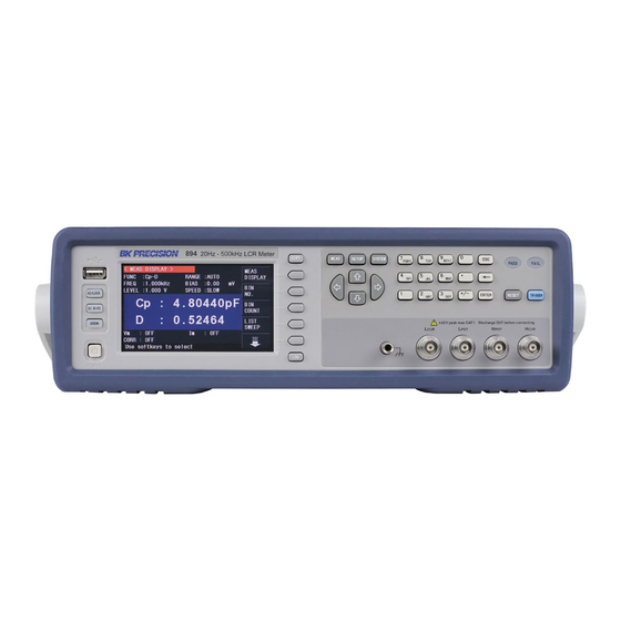
Models: 894, 895
500 kHz/1 MHz LCR Meter
USER MANUAL
GlobalTestSupply
www.
.com
Find Quality Products Online at:
sales@GlobalTestSupply.com
Table of
Contents
Previous
Page
Next
Page
1
2
3
4
5
Advertisement
Table of Contents
Need help?
Do you have a question about the 894 and is the answer not in the manual?
Ask a question
Questions and answers
Related Manuals for BK Precision 894
Measuring Instruments BK Precision 875B Instruction Manual
Digital lcr meter (37 pages)
Measuring Instruments BK Precision 878B Instruction Manual
Dual display lcr meter (142 pages)
Measuring Instruments BK Precision 879B Instruction Manual
Dual display lcr meter (142 pages)
Measuring Instruments BK Precision 880 Instruction Manual
Dual display lcr (71 pages)
Measuring Instruments BK Precision 830C Instruction Manual
Dual display capacitance meter (113 pages)
Measuring Instruments BK Precision 890C Instruction Manual
Dual display capacitance meter (113 pages)
Measuring Instruments BK Precision 8540 Instruction Manual
60v/30a/150w dc electronic load (23 pages)
Measuring Instruments BK Precision 895 User Manual
500 khz/1 mhz lcr meter (112 pages)
Measuring Instruments BK Precision 8500B Series User Manual
Programmable dc electronic loads (77 pages)
Measuring Instruments BK Precision 889B Manual
(30 pages)
Measuring Instruments BK Precision 830B Manual
(59 pages)
Measuring Instruments BK Precision 890B Manual
(59 pages)
Measuring Instruments BK Precision 8550 Series User Manual
Programmable вс electronic loads (58 pages)
Measuring Instruments BK Precision 8551 User Manual
Programmable вс electronic loads (58 pages)
Measuring Instruments BK Precision 885 Operating Manual
Lcr meter (91 pages)
Measuring Instruments BK Precision 4070A User Manual
21.5mhz multi function arbitrary waveform generator (88 pages)
This manual is also suitable for:
895
Table of Contents
Print
Rename the bookmark
Delete bookmark?
Delete from my manuals?
Login
Sign In
OR
Sign in with Facebook
Sign in with Google
Upload manual
Upload from disk
Upload from URL


Need help?
Do you have a question about the 894 and is the answer not in the manual?
Questions and answers