
Related Manuals for BK Precision 2841


Summary of Contents for BK Precision 2841
- Page 1 22820 Savi Ranch Parkway Yorba Linda, CA 92887 www.bkprecision.com © 2017-2020 B&K Precision Corp. Printed in China v090820...
- Page 2 2841 Start 2841 DC Resistance Meter USER MANUAL...
-
Page 3: Safety Summary
Safety Summary The following safety precautions apply to both operating and maintenance personnel and must be followed during all phases of operation, service, and repair of this instrument. Before applying power to this instrument: Read and understand the safety and operational information in this manual. ... - Page 4 Do not use this instrument in an electrical environment with a higher category rating than what is specified in this manual for this instrument. You must ensure that each accessory you use with this instrument has a category rating equal to or higher than the instrument's category rating to maintain the instrument's category rating.
- Page 5 Probes and Test Leads If the instrument is used with test leads or probes, the test leads or probes must have a safety category rating at least as high as that of the instrument to maintain the instrument's safety category rating. ...
- Page 6 In the presence of noxious, corrosive, or flammable fumes, gases, vapors, chemicals, or finely-divided particulates. In relative humidity conditions outside the instrument's specifications. In environments where there is a danger of any liquid being spilled on the instrument or where any liquid can condense on the instrument.
- Page 7 If the instrument is damaged, appears to be damaged, or if any liquid, chemical, or other material gets on or inside the instrument, remove the instrument's power cord, remove the instrument from service, label it as not to be operated, and return the instrument to B&K Precision for repair.
- Page 8 Hazardous voltages may be present in unexpected locations in circuitry being tested when a fault condition in the circuit exists. Fuse Replacement Fuse replacement must be done by qualified service-trained maintenance personnel who are aware of the instrument's fuse requirements and safe replacement procedures. Disconnect the instrument from the power line before replacing fuses.
- Page 9 Do not place heavy objects on the instrument. Do not obstruct cooling air flow to the instrument. Do not place a hot soldering iron on the instrument. Do not pull the instrument with the power cord, connected probe, or connected test lead.
-
Page 10: Compliance Statements
Compliance Statements Disposal of Old Electrical & Electronic Equipment (Applicable in the European Union and other European countries with separate collection systems) This product is subject to Directive 2002/96/EC of the European Parliament and the Council of the European Union on waste electrical and electronic equipment (WEEE), and in jurisdictions adopting that Directive, is marked as being put on the market after August 13, 2005, and should not be disposed of as unsorted municipal waste. -
Page 11: Ce Declaration Of Conformity
CE Declaration of Conformity This instrument meets the requirements of the Low Voltage Directive, 2006/95/EC and Electromagnetic Compatibility Directive, 2004/108/EC using the standards referenced below: Low Voltage EN 61010-1:2010 EN 61010-2-030:2010 EMC Directive EN 61326-1:2013 EN 61000-3-2:2006+A1:2009+A2:2009 EN 61000-3-3:2008... -
Page 12: Safety Symbols
Safety Symbols Refer to the user manual for warning information to avoid hazard or personal injury and prevent damage to instrument. Electric Shock hazard On (Supply). This is the AC mains connect/disconnect switch on the front of the instrument. Off (Supply). This is the AC mains connect/disconnect switch on the front of the instrument. -
Page 13: Notations
Notations TEXT – Denotes a softkey. TEXT – Denotes a front panel button. -
Page 14: Table Of Contents
Table of Contents Safety Summary ........................66 Compliance Statements ....................... 73 CE Declaration of Conformity ....................74 Safety Symbols ........................75 Notations ..........................76 General Information ...................... 81 Product Overview ......................81 Package Contents ......................81 Dimensions ........................82 Front Panel Overview ...................... 83 Rear Panel Overview...................... - Page 15 3.3.1 OPTIONS ......................100 3.3.2 BIN ........................100 3.3.3 BIN BEEP ......................100 3.3.4 NG COLOR & GD COLOR ................... 100 Statistics Display ......................101 3.4.1 OPTIONS ......................102 3.4.2 EdgeMode ......................102 3.4.3 Status ........................ 102 3.4.4 Statistical Analysis Parameters ................ 103 Setup Menus ........................
- Page 16 4.4.5 Bus Mode ......................116 4.4.6 Baud Rate ......................116 4.4.7 EOC Signal ......................116 4.4.8 Err.OUT signal ....................117 4.4.9 Setting Time and Date ..................118 LAN SETUP ........................118 FILE MANAGER ......................120 File Structure ......................... 120 5.1.1 Saving Configuration Files ................
- Page 17 10 LIMITED THREE-YEAR WARRANTY ................138 lxxx...
-
Page 18: General Information
Its maximum accuracy of 0.01% and its range, 0.1 μΩ to 110 MΩ are vividly displayed on the color LCD touchscreen in 5½ digits. The 2841 is ideal for testing resistances found in PCBs, conductors, relay contacts, interconnections, welding-holes as well as resistors and bigger components. -
Page 19: Dimensions
Note: User manual is available for download at www.bkprecision.com 1.3 Dimensions The 2841 dimensions are approximately: 255 mm x 110 mm x 361 mm (10.04 in x 4.33 in x 14.22 in) (W x H x D). Figure 34 - Dimensions... -
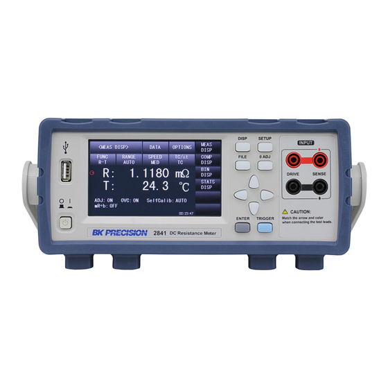
Page 20: Front Panel Overview
1.4 Front Panel Overview Figure 35 - Front Panel Front Panel Description ① USB Interface ② LCD Touchscreen ③ DISP ④ FILE ⑤ SETUP ⑥ 0 ADJ ⑦ Test Terminals ⑧ TRIGGER ⑨ ENTER ⑩ Universal Arrow Keys ⑪ Power... -
Page 21: Rear Panel Overview
1.5 Rear Panel Overview Figure 36 - Rear Panel Rear Panel Description ① Ground Terminal ② RS-232 Serial Interface ③ Power Socket ④ Fuse Socket ⑤ Temperature input ⑥ USB Interface ⑦ LAN Interface ⑧ Handler Interface... -
Page 22: Keypad Overview
1.6 Keypad Overview Figure 37 - Keypad Keypad Description DISP key Enters the main measurement display and opens display options SETUP key Enters the setup menu. FILE key Enters the internal and external file manager 0 ADJ key Executes zero adjustment function TRIGGER key Manual trigger when trigger mode is set to MANU (manual) ENTER key... -
Page 23: Display Overview
1.7 Display Overview Figure 38 - Display Display Description ① Display Name - Shows the current display name ② DATA – Access to save screen and file management (internal or external) ③ OPTIONS – Access to additional display specific functions ④... -
Page 24: Getting Started
2 Getting Started Before connecting and powering up the instrument, please review and go through the instructions in this chapter. 2.1 Input Power Requirements The supply has a universal AC input that accepts line voltage input within: Voltage: 110 V – 240 V (±10%) Frequency: 50 Hz –... -
Page 25: Input Connections
Check and/or Change Fuse 1. Locate the fuse box next to the AC input connector in the rear panel (see Figure 3 - Rear Panel) 2. With a small flat blade screwdriver, insert into the fuse box slit to pull and slide out the fuse box as indicated below. -
Page 26: Preliminary Check
Figure 40 Connection Alignment Figure 41 Do Not Connect Vertically 2.4 Preliminary Check Complete the following steps to verify that the instrument is ready for use. 1. Verify AC Input Voltage Verify and check to make sure proper AC voltages are available to power the instrument. The AC voltage range must meet the acceptable specification as explained in Input Power Requirements. -
Page 27: Cable Calibration
Figure 42 - Boot Screen If password protection is enabled, the user will have to input the password to operate the unit. The default password is 2841 See 4.3.4 Password for more details. 2.5 Cable Calibration The resistance in the 4-terminal cables can be compensated for through the zero adjustment (0 ADJ) function. - Page 28 Blue – DRIVE- White – DRIVE+ Black – SENSE- Red – SENSE+ Figure 43 Short Connection...
-
Page 29: Front Panel Operation
3 Front Panel Operation The touchscreen menu displays contains all measurement and function options. The universal arrow keys along with the ENTER key can also be used to navigate the touchscreen. The measurement display menu consists of a primary menu and a secondary menu shown to the right of the screen. -
Page 30: Measurement Display
Figure 45 Alphanumeric Keypad 3.1 Measurement Display The Measurement Display (MEAS DISP) is the main page for displaying resistance and temperature measurements. See Error! Reference source not found. Error! Reference source t found. for additional options. To access the page press the DISP button and select MEAS DISP in menu options. -
Page 31: Options
Touch the measurement result area to zoom the display, removing the menu options from the display. Touch again to return to the normal screen display. Figure 47 Zoom Display The following parameters are accessible from the Measurement Display. OPTIONS FUNC RANGE SPEED TC/∆t... -
Page 32: Func
OVC (ON/OFF): Toggle Offset Voltage Compensation on and off. OVC increases accuracy at the cost of increased measurement time. Note: OVC - When two different materials come into contact, a thermo electromotive force (EMF) will be generated on the contact surface and will vary with the ambient temperature. The higher the ambient temperature is, the larger the thermo electromotive force will be. -
Page 33: Speed
AUTO: Automatically selects the range mode depending on the resistance detected. HOLD: Lock to the current resistance measurement range. ↑ (+): Increase measurement range and sets the measurement to HOLD. ↓ (- ): Decrease measurement range and sets the measurement to HOLD. If FUNC is set to T, resistance RANGE menu options are disabled and will display AUTO. -
Page 34: Comparator Display
3.2 Comparator Display The Comparator Display (COMP DISP) page compares the resistance measurement to absolute limits or a nominal value ± a percentage. The total count (TOT) is incremented and the result is categorized as high (HI), low (LO), or in (IN). To access the page press the DISP button and select COMP DISP in menu options. -
Page 35: Options
The following parameters are accessible from the Comparator Display. OPTIONS COMP COMP MODE • DISP • OFF • % • COMP BEEP • ON • NOM • COUNT • % • COUNT CLEAR • ABS • SAVE DATA • HIGH •... -
Page 36: Bin Display
Figure 50 Comparator Display Percent Error ABS (Absolute): The user can set absolute HIGH and LOW limits. The instrument will compare the measured value to the absolute limits and determine if the DUT is HI (above the upper limit), LO (below the lower limit), or IN (within limits). 3.3 Bin Display The Bin Display (BIN DISP) page places the resistance measurement in up to 10 user-defined bins. - Page 37 The following parameters are accessible from the Bin Display. OPTIONS BIN BEEP NG COLOR GD COLOR • DISP • OFF • OFF • OFF • OFF • SAVE DATA • ON • NG • GRAY • GRAY • GD • RED •...
- Page 38 OFF: Nothing is displayed when the measurement result differs from the bin setting. GREY: When the measurement result differs from the bin setting, the corresponding bin will be displayed in grey. RED: When the measurement result differs from the bin setting, the corresponding bin will be displayed in red.
- Page 39 The following parameters are accessible from the Statistical Display. OPTIONS EdgeMode STATUS •CLEAR •% •OFF •TRIG •NOM •ON •SAVE DATA •% •ABS •Hi •Li 3.4.1 OPTIONS The OPTIONS key allows the user to access the additional statistics options menu. The measurement options are: ...
- Page 40 OFF: When OFF is selected, the statistic measurements are disabled. All other functions and buttons are enabled. 3.4.4 Statistical Analysis Parameters Parameter Variable Description Formula ∑ �� MEAN ��̅ Average value ��̅ = �� �� STDEV Population ∑ (�� − ��̅ ) Standard ��...
- Page 41 Min: Minimum measurement result among the current data set. MinIndex: Sample index number that corresponds to the minimum measurement result. Example: NOM, % is 100±10% Sample Index Result (Ω) 100.4 101.6 103.7 98.4 87.9 112.1 86.5 Results: Hi = 1, Lo = 2, In = 5, Max = 112.1, MaxIndex = 6, Min = 86.5, MinIndex = 8...
- Page 42 4 Setup Menus The setup menus allow the user to have more control the measurement operations, functions, and calculations. The universal arrow keys along with the ENTER key can also be used to navigate the touchscreen. The setup page menus consists of a primary menu and a secondary menu shown to the right of the screen.
- Page 43 The following parameters are accessible from the Measurement Setup page: mR+b FUNC RANGE TRIG TRIG DELAY AVERAGE •OFF •R •AUTO •INT •AUTO •1 - 255 •ON •R-T •HOLD •MAN •MANU •T •↑ •EXT •INPUT •LPR •↓ •BUS •LPR-T Meas 200 mΩ DETECT SPEED Adjust...
- Page 44 Note: The instrument is in waiting mode until triggered. 4.1.5 TRIG DELAY The TRIG DELAY enables the user to select between AUTO and MANU (manual) modes. Automatic trigger delay is determined by Table 11 Auto Trigger Delay. To set a manual trigger delay: 1.
- Page 45 MANU: Detection time manually set. INPUT: Opens numeric keypad to modify manual detection timing. 4.1.9 Meas Mode The instrument has an internal 10 nF capacitor that can be connected or disconnected across the terminals. Commonly used when measuring large resistors and inductors. The user can select between the following modes: ...
- Page 46 The following parameters are accessible from the Temperature Compensation Setup page: ∆t Analog TC/∆t T.SENS •t0 (°C) •R1 (Ω) •V1 (V) •OFF •Pt •αt0 (ppm) •t1 (°C) •V2 (V) •TC •AnLG_In •k •T1 (°C) •∆t •T2 (°C) Note: 1. The temperature probe detects ambient temperature, not DUT surface temperature. 2.
- Page 47 4.2.3 Types of Temperature Sensors The instrument is designed to use two types of temperature input: Pt and Analog Input. Touch the T.SENS key, the following menu options will be displayed: Pt: Provided temperature probe. AnLG_In: Linearly converts probe input voltage (0 to 2 V) into temperature based on Analog Input settings.
- Page 48 – DUT temperature at the start of the thermal test. – Ambient temperature at the end of the thermal test. – Variance ration of the temperature coefficient when the conductor is at 0 °C. Example: A copper DUT is measure before operation: is 100 mΩ, is 20 °C.
- Page 49 V2, T2 V1, T1 Figure 55 - Analog Input Voltage vs Temperature Note: V1 and V2 range from 0.00V to 2.00V while T1 and T2 range from -99.9 °C to 999.9 °C. 4.3 BIN SETUP The BIN SETUP page is where the user can define the parameters for up to 10 bins. To access the page press the SETUP button and select BIN SETUP in menu options.
- Page 50 The following parameters are accessible from the Bin Setup page: OPTIONS BIN NO. 0 to 9 STATE • BIN MODE • PgUp • DEL • OFF • BIN BEEP • PgDn • ON • BIN CLEAR • BIN OUT 4.3.1 OPTIONS The OPTIONS key allows the user to access the additional bin setup options menu.
- Page 51 NOM: Input the nominal value. %: Input the percentage value. 4.4 SYSTEM SETUP The SYSTEM SETUP page is where the user can change instrument settings. To access the page press the SETUP button and select SYSTEM SETUP in menu options. Figure 57 - System Setup The following parameters are accessible from the System Setup page: OPTIONS...
- Page 52 6. Input the new password a second time and press ENTER to confirm. 7. Prompt: “Confirm new password” 8. The <SYSTEM SETUP> page will be displayed and the password modification is complete. 9. Prompt: “Password modify ok” Note: The default password is 2841...
- Page 53 4.4.5 Bus Mode Press Bus Mode to select the communication interface in the menu options. All interfaces are accessible on the rear panel. RS232C LAN USBTMC USBVCOM 4.4.6 Baud Rate Press Baud Rate to select from the following six baud rates: ...
- Page 54 Figure 58 External Trigger Timing Figure 59 Internal Trigger Timing 4.4.8 Err.OUT signal The Err.OUT signal can be found on pin 11 of the [Handler]. A measurement error occurs when the instrument has lost contact with a DUT. Press Err.OUT to select between: ...
- Page 55 AC Frequency Press AC Freq to select the power supply frequency: 50Hz or 60Hz. Selecting the correct frequency reduces the power line noise’s influence on the instrument. 4.4.9 Setting Time and Date Touch the time or date digits to open the modification menu. For example: 9 o’clock 13 minute and 25 second a.m.
- Page 56 The LAN SETUP page is where the user can setup the instrument up to connect over a Local Area Network (LAN). To access the page press the SETUP button and select LAN SETUP in menu options. Figure 60 LAN SETUP The user can modify all addresses on the screen by touching the number zone and accessing the numeric keypad.
- Page 57 5 FILE MANAGER The file manager menu is used to save and load parameter configuration files (.STA) set by the user. These files can be saved to the internal (I) non-volatile memory or an external (E) USB flash drive. Insert an empty USB flash drive to the front panel USB port and wait for the drive to initialize (about five seconds).
- Page 58 4. Select SAVE. If an existing STA file is select, it will be overwritten. 5. Select YES to continue. Select NO to cancel. 6. An alphanumeric keypad will open. Type in desired file name. Press Enter. Or Esc to cancel. 5.1.2 Load Configuration Files 1.
- Page 59 5.2 SAVE SCREEN This function can be found in the DATA menu on most displays. Press SAVE SCREEN and a screenshot will be saved in the PIC folder mentioned above. The name assigned to the screenshot will start at zero, but if there are other screenshots from this units in that folder, it will assign the lowest value possible.
- Page 60 6 Specifications All specifications apply to the unit after: Temperature Stabilization time: 30 mins Operating Temperature: 23 °C ± 5 °C Relativity Humidity: ≤ 80% Specifications are subject to change without notice. Rd = Measured Value Fs = Full range 6.1 Specifications Resistance Measurement Reading Digits...
- Page 61 Display Digits SLOW2, SLOW1, MED FAST Display Digits 6 digits 5 digits Temperature range 3 digits, maximum display 3 digits, maximum display number: 999.9 °C number: 999.9 °C Measurement Function Resistance FAST: 7 ms, MED: 22 ms, SLOW1: 102 ms, SLOW2: 402 ms Measurement Time (+20 ms when DISPLAY is ON) Temperature...
- Page 62 6.2 Basic Accuracy for Resistance Measurement Range ± (Rd% + Fs%) Current Open display Range Circuit SLOW2 SLOW1 FAST value Voltage 20 mΩ 20.0000 0.25+0.015 0.25+0.017 0.25+0.02 0.25+0.025 1A ±5% 5Vmax ± 0.2000 0.25+0.001 0.25+0.001 0.25+0.001 0.25+0.004 mΩ 200 mΩ 200.000 0.25+0.006 0.25+0.008 0.25+0.012...
- Page 63 6.3 Resistance Measurement at Low Voltage Basic Accuracy Accuracy in one year (23±5℃) Range Maximum ± (Rd% + Fs%) Curr Open display Circuit SLOW2 SLOW1 FAST value Rang Voltage 2 Ω 2000.00 ± 0.05+0.01 0.05+0.012 0.05+0.015 0.05+0.02 60mVmax 020.00 mΩ A±5 ON 0.05+0.001 0.05+0.001...
- Page 64 6.4 Timing The measurement speed of the instrument is determined by the following factors: Integral sampling period (approx. 5ms) Average times (measurement times) Measurement delay time (a time starting from the measurement start-up to the measurement beginning) ...
- Page 65 *Accuracy=0.3% x measured value ± 0.5 °C 6.6 Accuracy for Temperature Measurement (Analog Input) Analog Input Input voltage range 0 to 2 V Temperature range display -99.9 °C to 999.9 °C Resolution 1 mV Accuracy ±1% T ± 3 mV –...
- Page 66 7 Remote Control The instrument has RS232, USB (virtual COM), and LAN interfaces for remote control. This chapter will describe how users can remotely operate the instrument and use SCPI (Standard Commands for Programmable Instruments) commands via these interfaces. 4.3.5 Bus Mode must be in the respective interface mode in order to communicate.
- Page 67 Parameter Description Baud rate 9600, 19200, 28800, 38400, 48000, 57600, and 115200. Parity and None/8 bits data bit Stop bit Flow control None The RS232C interface does not support hardware flow control (only transmit, receive, and ground pins are used). The programmer should be aware of this communication error.
- Page 68 7.4 LAN (Ethernet) The instrument can be controlled via LAN interface. Connect over Ethernet cable to a network or directly to a computer. Enter the instrument’s IP address into a browser. Navigate the interface with the menu pages on the left of the screen. 7.5 Remote Commands The instrument supports some SCPI commands and some instrument specific commands.
- Page 69 8 Handler Interface The instrument is equipped with a 50 pin Handler interface for external control and outputting measurement and sorting results. If BIN OUT is BCD, pins 14 to 50 are BCD outputs and BIN, OB, and OUT are disabled. Mating connector: Amphenol PN:57-30500 Terminals and Their Descriptions: Signal name...
- Page 70 TRIG:External trigger will take one measurement while this signal transitions from high to low. 1. This signal will be ignored if the trigger setting is set to internal trigger. 2. This signal will be ignored when no 4-terminal connector attached. 3.
- Page 71 File Number LOAD4 LOAD3 LOAD2 LOAD1 LOAD0 Note: The file load cannot be controlled through RS232.
- Page 72 8.2 Output Signal ERR: Error signal output is divided into synchronous measurement error signal output and asynchronous measurement error signal output. The measurement error signal is outputted together with EOC as synchronous error signal output, not asynchronous error signal output. INDEX: Transitions from low to high to indicate that the instrument measurement is finished.
- Page 73 8.4 Isolated Output Each input and output signal is isolated by a photoelectric coupler. The output voltage of each line is determined by the connection between a pull-up resistor and an externally applied voltage (EXTV). The output circuit is shown as follows: External control input circuit is shown as follows:...
- Page 74 9 SERVICE INFORMATION Warranty Service: Please go to the support and service section on our website at www.bkprecision.com to obtain a RMA #. Return the product in the original packaging with proof of purchase to the address below. Clearly state on the RMA the performance problem and return any leads, probes, connectors and accessories that you are using with the device.
- Page 75 10 LIMITED THREE-YEAR WARRANTY B&K Precision Corp. warrants to the original purchaser that its products and the component parts thereof, will be free from defects in workmanship and materials for a period of three years from date of purchase. B&K Precision Corp. will, without charge, repair or replace, at its option, defective product or component parts.
- Page 76 22820 Savi Ranch Parkway Yorba Linda, CA 92887 www.bkprecision.com © 2017-2020 B&K Precision Corp. Printed in China v090820...
Need help?
Do you have a question about the 2841 and is the answer not in the manual?
Questions and answers