Table of Contents
Advertisement
Quick Links
Download this manual
See also:
User Manual
Advertisement
Table of Contents

Related Manuals for BK Precision 5335B


Summary of Contents for BK Precision 5335B
- Page 1 5335B Power Meter User Manual 1.800.561.8187 information@itm.com www. .com...
- Page 2 Safety Summary The following safety precautions apply to both operating and maintenance personnel and must be followed during all phases of operation, service, and repair of this instrument. Before applying power to this instrument: • Read and understand the safety and operational information in this manual. •...
- Page 3 SAFETY SUMMARY You must ensure that each accessory you use with this instrument has a category rating equal to or higher than the instrument’s category rating to maintain the instrument’s category rating. Failure to do so will lower the category rating of the measuring system. Electrical Power This instrument is intended to be powered from a CATEGORY II mains power environment.
- Page 4 SAFETY SUMMARY This instrument is intended to be used in an indoor pollution degree 2 environment. The operating temperature range is 0 C to 40 C and 20% to 80% relative humidity, with no condensation allowed. Measurements made by this instrument may be outside specifications if the instrument is used in non-o ice-type environments. Such environments may include rapid temperature or humidity changes, sunlight, vibration and/or mechanical shocks, acoustic noise, electrical noise, strong electric fields, or strong magnetic fields.
- Page 5 SAFETY SUMMARY instrument’s fuse requirements and safe replacement procedures. Disconnect the instrument from the power line before replacing fuses. Replace fuses only with new fuses of the fuse types, voltage ratings, and current ratings specified in this manual or on the back of the instrument. Failure to do so may damage the instrument, lead to a safety hazard, or cause a fire.
-
Page 6: Ce Declaration Of Conformity
SAFETY SUMMARY CE Declaration of Conformity This instrument meets the requirements of: EMC Directive • EN 61326-1 2006 • EN 61000-3-2-2006 • EN 61000-3-3:1995 1.800.561.8187 information@itm.com www. .com... -
Page 7: Safety Symbols
SAFETY SUMMARY Safety Symbols Refer to the user manual for warning information to avoid hazard or personal injury and prevent damage to instrument. Electric Shock hazard Alternating current (AC) Chassis (earth ground) symbol. Ground terminal On (Power). This is the In position of the power switch when instru- ment is ON. -
Page 8: Table Of Contents
Contents Safety Summary CE Declaration of Conformity ......... . . EMC Directive . - Page 9 viii CONTENTS 4.4.1 Filter ..........Averaging Function .
- Page 10 CONTENTS 11.3.1 Equipment cleaning ......... 11.3.2 Initialize .
-
Page 11: General Information
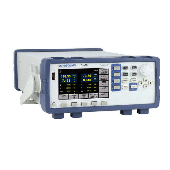
Chapter 1 General Information Note: The contents of this manual and included specifications are subject to change go to for the latest version. (Manual version: 2017-10-13 ) Figure shows a schematic Diagram of Front Panel of BK5335B Series Power Meter and Diagram of Key Functions. -
Page 12: Front Panel
CHAPTER 1. GENERAL INFORMATION 1.2 Front Panel Figure 1.1: Front Panel Power Bu on Rotary Knob 4.3” LCD Arrow Keys So -keys Main Functions So -keys Menu, Enter, ESC Print (Screen Capture) Name and function Waveform Display key: press to view waveforms. See Chapter Harmonic Measurement key: For viewing harmonic measurements. -
Page 13: Rear Panel Summary
CHAPTER 1. GENERAL INFORMATION 1.3 Rear Panel Summary Figure 1.2: Rear View GPIB Connector AC Line LAN Connector External Current Sensor USB Connector Voltage Input RS-232 Connector Current Shunt Input Synchronization BNC 1.4 Measurement Connection Setup Depending on the amount of current that will flow through the meter, 2 configurations are specified. 1. - Page 14 CHAPTER 1. GENERAL INFORMATION Figure 1.3: Current terminal cover Figure 1.4: Low Current Wiring Setup Figure 1.5: High Current Wiring Setup 1.800.561.8187 information@itm.com www. .com...
-
Page 15: Wiring External Current Sensors
CHAPTER 1. GENERAL INFORMATION Figure 1.6: External Sensor Interface: DE-9 Connector Pin # Description +12 V -12 V Signal GND Voltage Current Table 1.1: External Sensor Connector Pinout 1.5 Wiring External Current Sensors This power meter accepts a wide range of external current sensors. Measurement is achieved by applying a scaling factor to the voltage sensed at the external sensor input. -
Page 16: Power Up
An AC input fuse is necessary when powering the instrument. Refer to Table for the fuse requirements. Model Fuse Specification (110 V) Fuse Specification (220 V) 5335B T 10 A, 250 V T 6.3 A, 250 V Table 1.2: Required Fuses 1.6.2.1 Fuse Replacement 1. -
Page 17: Menu
Chapter 2 Menu Configuration of system-wide se ings is done from the “Menu”. Pressing the bu on enters the configuration/system menu, Figure 2.1. From the main menu, the so -keys at the bo om of the screen provide access to the configuration screens. See Table 2.1 MENU >... -
Page 18: System Information Menu
CHAPTER 2. MENU Function Description SYSTEM INFO System details, Model, Serial, etc. . . COMM CONFIG Setup the communication interfaces SYSTEM CONFIG Set date, time, beep and brightness SELF TEST Perform a self diagnostic INITIAL Reset device se ings Table 2.2: System Menu sub-menus Figure 2.2: System Info Screen 2.1.1 System Information Menu Information about the device is listed in this menu. -
Page 19: System Configuration Menu
CHAPTER 2. MENU Figure 2.3: COMM Configuration - RS-232 Figure 2.4: COMM Configuration - USB 2.1.2.3 GPIB The GPIB interface may be configured to addresses 1 through 30. Use the arrow keys to select the numeric field beside “GPIB Address” and use the rotary knob to change the value. The user may select each digit by the arrow keys as well. - Page 20 CHAPTER 2. MENU Figure 2.5: COMM Configuration - GPIB Figure 2.6: COMM Configuration - LAN (DHCP) Figure 2.7: COMM Configuration - LAN (Manual (static)) 1.800.561.8187 information@itm.com www. .com...
-
Page 21: Self Test
CHAPTER 2. MENU Figure 2.8: System Config Menu Figure 2.9: System Self Test 2.1.4 Self Test The unit has a built in self test. This function tests the LEDs, the screen and some of the internal electronics, Figure 2.9. When the test is running, it cycles through colors on the LCD, and lights up the individual LEDs that illuminate the front panel bu ons. -
Page 22: Menu > Setup Menus
CHAPTER 2. MENU Figure 2.10: System Initialize Menu Figure 2.11: Setup Information Screen 2.2 MENU > SETUP menus From the “MENU” function, the next page is the “SETUP” so -key (Figure 2.11. This screen essentially gives a summary of the se ings controlling measurements. 1.800.561.8187 information@itm.com www. - Page 23 CHAPTER 2. MENU Field Description Average Listing of the average mode se ings. See Averaging Setup Sync Source The measurement synchronization signal source. See ?? Line Filter The state of the line filter. Update rate How o en to measure? Freq Filter The state of the frequency filter.
- Page 24 CHAPTER 2. MENU Figure 2.14: Ratio Set Menu Figure 2.15: Ratio Set Menu Figure 2.16: Calibration Menu 1.800.561.8187 information@itm.com www. .com...
-
Page 25: Averaging Setup
CHAPTER 2. MENU Figure 2.17: Ratio Setup Menu 2.2.1 Averaging Setup 2.2.2 External Sensor Setup 2.2.3 Other se ings 2.2.4 Inrush Measurement Setup 2.3 CAL ZERO 2.4 RATIO SET This se ing has the e ect of scaling the measured value of the current and voltage. For example, a 116 V signal becomes 232 V when the “Voltage Ratio”... -
Page 26: External Current Sensor
Chapter 3 External Current Sensor More information to be added in future versions of this documentation. When using an external current sensor, the power meter has more current range options. See details Section ??. Sensor Input Crest Factor Ranges EXT1 Crest Factor 3 (CF=3) 2.5 V, 5 V, 10 V EXT1... -
Page 27: Front Panel Operation
Chapter 4 Front Panel Operation 4.1 Measurement Setup Central to se ing the proper range of the instrument is the Crest Factor. Crest factor is the ratio of the peak value of a waveform to the RMS value of the waveform. For example, a perfect sine wave crest factor RMS value is 0.707*Peak. -
Page 28: Voltage And Current Range
CHAPTER 4. FRONT PANEL OPERATION 1. In the “Meter” interface Press the so key corresponding to either “U-RANGE” or “A-RANGE”, and use the knob or the arrow keys to select the voltage or current range desired. See Table 2. Press the “Enter” key to confirm the se ing. Otherwise the instrument will automatically confirm and exit the se ing a er 5 seconds of no activity. -
Page 29: Measurement Interval
CHAPTER 4. FRONT PANEL OPERATION 4.3 Measurement interval The measurement interval, the time during which data is taken. The fundamental frequency of the measured signals restricts the measurement intervals that yield meaningful results. For example, measuring 10Hz with an interval of less than the 0.5s se ing will not yield stable results. The unit needs a number of cycles to be present to determine the frequency, and measurement intervals are not synchronized to the input. -
Page 30: Filter And Crest Factor Se Ing
CHAPTER 4. FRONT PANEL OPERATION The data updating cycle refers to the cycle used for calculating sam- pling data of the measurement function. It is identical to the set value of the data updating rate. The slope refers to signal changes from low level to high level (rising edge) or from high level to low level (descending edge). -
Page 31: Averaging Function
CHAPTER 4. FRONT PANEL OPERATION more accurate. When the frequency filter is switched on, the voltage or current of no more than 200Hz can be measured. The cuto frequency is 500HZ. Line filter It is inserted in the voltage and current measurement circuit and has direct influence on measurement of the voltage, current and power. -
Page 32: Index Averaging
CHAPTER 4. FRONT PANEL OPERATION 4.5.1 Index averaging The value displayed a er the nth index averaging, (D , the value dis- played a er the first averaging, is equal to M1) The value displayed a er the (n-1)th index averaging the nth measured data. - Page 33 Chapter 5 Meter Display The 5335B has 3 configurable display formats. Each format also allows for 5 di erent configured sets of measurement. 1 large and 6 small, 4 large and 6 small, or 12 small measurements may be displayed. See Figures 5.1, 5.2, 5.3.
- Page 34 CHAPTER 5. METER DISPLAY Figure 5.2: 4 main measurements Figure 5.3: 12 main measurements 1.800.561.8187 information@itm.com www. .com...
-
Page 35: Waveform Display Function
Chapter 6 Waveform Display Function The 5335B power meter displays waveform representations of the sampled data measured. This function is designed to be similar to an oscilloscope with many of the typical functions of oscilloscopes available, like trigger, run/stop and single trigger. The capture of data is not limited to that displayed onscreen, the measurement interval is also involved. -
Page 36: Vertical Calibration
CHAPTER 6. WAVEFORM DISPLAY FUNCTION Figure 6.1: Waveform Display Details Trigger status Instruction When the trigger mode is set as Auto, the trigger status Auto will be displayed a er Auto triggering. When the trigger mode is set as Auto, the trigger status will be Auto in the case of Auto? no triggering? When the trigger mode is set as Normal, the trigger status Trig will be displayed... -
Page 37: Trigger Waveform
CHAPTER 6. WAVEFORM DISPLAY FUNCTION distance between the trigger point and the horizontal center will be indicated. The trigger point is displayed along the top of the display grid. 6.0.5 Trigger waveform When the specified trigger conditions are satisfied, the trigger waveform will be displayed, and the triggering time point is called trigger point. -
Page 38: External Trigger Input (Ext)
CHAPTER 6. WAVEFORM DISPLAY FUNCTION Figure 6.2: Trigger Setup Screen Projects Specification Interface type BNC interface Input level Minimum pulse width 1µs Trigger delay time Within (1µs + 3 sampling cycles) Table 6.3: External Trigger Input Specifications 2. In the waveform display interface Press the so key corresponding to the “TIRG SET” parameter to enter the trigger se ing interface, as shown below. -
Page 39: Harmonic Measurement Function
The voltage, current, active power, reactive power and phase of harmonics and total harmonic distortion (THD) factor can be tested in the harmonic mode. In addition, the 5335B power meter can be used for multiple harmonic measurements, 50-order harmonics of the fundamental frequency at most. -
Page 40: Introduction Of Harmonic Information
CHAPTER 7. HARMONIC MEASUREMENT FUNCTION 7.1.1 Introduction of harmonic information When the “BAR” bu on is selected in the harmonic measurement interface, the bar chart of harmonic measurement results will be displayed. The bar chart is used for displaying the percentage of di erent harmonics. Harmonics can be displayed in the whole sequence, odd sequence and even sequence. -
Page 41: Parameter Descriptions
CHAPTER 7. HARMONIC MEASUREMENT FUNCTION Abbreviations Instruction U(V) Voltage φUI( ) Phase di erence of k-order harmonic voltage and harmonic current A(mA) Current φUU( ) Phase di erence of harmonic voltage U(k) and fundamental wave U(1) W(W) Active power φII( ) Phase di erence of harmonic current I(k) and fundamental waveI(1) S(VA) Apparent power... -
Page 42: Pll Source
7.2.2 PLL source In the harmonic mode, 5335B adopts PLL to multiply the frequency of the input signal. The frequency multiplication output signal is used as the A/D sampling clock in the instrument so as to achieve the purpose of synchronous sampling. -
Page 43: Harmonic Analysis Order
CHAPTER 7. HARMONIC MEASUREMENT FUNCTION 7.2.2.1 PLL source selection The voltage or current of the input unit can be selected as the PLL source. Used for determining the fundamental wave cycle as the reference for analysis of harmonic orders. The fundamental wave frequency of the PLL source is 10Hz to 1.2kHz. - Page 44 CHAPTER 7. HARMONIC MEASUREMENT FUNCTION is one-wave long, and the data measurement interval is 100ms. In this case, the harmonic measurement time is approximately morethan or equal to 150ms (data measurement interval and data processing time). Therefore, please select the data updating rate of 250ms or more for measurement and display of harmonic data. 1.800.561.8187 information@itm.com www.
-
Page 45: Integral Operation Function
8.1 Basic Concepts The 5335B power meter can be used for integral operation of the current and power of the input unit. Technical indicators can be calculated. In addition, the range can be switched automatically in the Buy and Sell modes according to the input level so as to accurately complete integrate measurement. -
Page 46: Introduction Of So Keys On The Interface
CHAPTER 8. INTEGRAL OPERATION FUNCTION Figure 8.2: Meter Display Parameter name Parameter descriptions Voltage range se ing: press the so key corresponding to this parameter to set the V_RANGE voltage range. Current range se ing: press the so key corresponding to this parameter to set the A_RANGE current range. -
Page 47: Integral Operation
CHAPTER 8. INTEGRAL OPERATION FUNCTION Character Function description Display the integral start and stop mode. Start mode: MANUAL and TIME Mode Stop mode: MANUAL, TIME and TINTerval. State Display the current status of the integral function. Start: displayed when the integral function is working. Stop: displayed when the integral function is interrupted, canceled or stopped. -
Page 48: Se Ing Of Integral Measurement Configuration
CHAPTER 8. INTEGRAL OPERATION FUNCTION Current integral Integral interrup- Function Integral rese ing status tion Functions related to set- tings of measurement pa- rameters Wiring Executable Unenforceable Unenforceable Measurement range Executable Unenforceable Unenforceable Filter Executable Unenforceable Unenforceable Averaging function Executable Unenforceable Unenforceable Synchronization... -
Page 49: Parameter Descriptions
CHAPTER 8. INTEGRAL OPERATION FUNCTION Operation steps 1. Press “Integ” to enter the integral measurement interface. 2. Press the so key corresponding to the “SETUP” parameter in the integral measurement interface to enter the integral parameter configuration interface. Press the “ ” bu on to select the required parameter, as shown in the figure below. -
Page 50: Integration
CHAPTER 8. INTEGRAL OPERATION FUNCTION 8.6 Integration When the integral measurement function is enabled, you can keep the current integral information and carry out the following operations: exit, start and stop. Specific steps are as follows: Operation steps 1. Press “Integ” to enter the integral display interface. 2. -
Page 51: Remote Operation
Chapter 9 Remote Operation There are four types of communication interfaces available:USB,Ethernet,GPIB and RS232.You can choose any one of them to communicate with a PC. 9.1 RS-232 Interface RS232 interface:use a cable with two COM interface (DB9) to connect power meter and PC. It can be activated by menu key on the front panel.All SCPI commands are available through RS-232 programming. -
Page 52: Rs-232 Communication Se Ings
CHAPTER 9. REMOTE OPERATION Pin # Signal Table 9.1: RS-232 (DE-9) Pinout cables or adapters must be used, as described under RS-232 connector. Note that even if the cable has the proper connectors for your system,the internal wiring may be incorrect. The interface cable must be connected to the correct serial port on your computer (COM1, COM2,etc.). -
Page 53: Gpib Interface
CHAPTER 9. REMOTE OPERATION 9.3 GPIB interface First conncet GPIB port of power meter to GPIB card of PC. They must be su icient contact and tighten the screws. And then set address. The address can be set from 0 to 30. 9.4 LAN interface Use a network cable to connect PC through LAN interface of the power meter. -
Page 54: Specifications
Chapter 10 Specifications The specifications listed below are valid and specified for the following conditions: • Warm up time of 30 minutes • Ambient temperature - 23 • Relative humidity 30 to 75% 1.800.561.8187 information@itm.com www. .com... - Page 55 Power Meter 5335B Specifications Specifications are subject to the following conditions Temperature: 23±5° C, humidity: 30 to 75% RH. Warm-up time: 30 minutes Model 5335B General Measurement Specifications Peak to peak, Maximum, Minimum, Average_rms, Average_rectified, DC, Voltage, Current Crest factor (current), Inrush (current)
- Page 56 Power Meter 5335B Specifications (cont.) Current Measurement Accuracy and Ranges CF= 3:5 mA, 10 mA, 20 mA, 50 mA, 100 mA, 200 mA, 0.5 A, 1 A, 2 A, 5 A, 10 A, 20 A Direct input range CF= 6:2.5 mA, 5 mA, 10 mA, 25 mA, 50 mA, 100 mA, 250 mA, 0.5 A, 1 A, 2.5 A, 5 A, 10 A CF = 3: 2.5 V, 5 V, 10 V...
- Page 57 Power Meter 5335B Specifications (cont.) Harmonic Measurement Parameters Measurement method PLL synchronization Frequency range PLL frequency source range 10 Hz to 1.2 kHz (typical) FFT data length 1024 Window function Rectangle Fundamental frequency (Fund. freq.) 10 Hz to 75 Hz...
-
Page 58: Routine Maintenance
11.2 Error Information References The 5335B power meter has a detailed error and prompt information function, so as to help the user to easily carry out positioning and measurement during measurement and use. This section describes all error information of the 5335B power meter as well as error causes and disposals. - Page 59 CHAPTER 11. ROUTINE MAINTENANCE Error information Error information explanation Error description The start time is less than the current time. Start time is less than cur- Possible cause The integral se ing is incorrect. rent Disposal Reset the integral start time. Error description The ending time is less than the current time.
-
Page 60: Daily Maintenance
CHAPTER 11. ROUTINE MAINTENANCE Error information Error information explanation Error description The oscilloscope function cannot be enabled. Scope openfail Possible cause Communication abnormality Disposal Check the communication cable. Error description Time se ing fails. Time set fail Possible cause Time se ing is illegal. Disposal Reset the system time. - Page 61 CHAPTER 11. ROUTINE MAINTENANCE Prompt information Explanation of prompt information Cal Zero is working! The instrument is calibrating the zero point. Cal Zero is completed! The instrument has completed zero point calibration. Test screen Self-inspection of LCD screen Test dsp Self-inspection of DSP.
- Page 62 CHAPTER 11. ROUTINE MAINTENANCE • Check whether the instrument displays error information. • Use other instruments instead of this instrument for confirmation. 1.800.561.8187 information@itm.com www. .com...
Need help?
Do you have a question about the 5335B and is the answer not in the manual?
Questions and answers