Sign In
Upload
Download
Table of Contents
Contents
Add to my manuals
Delete from my manuals
Share
URL of this page:
HTML Link:
Bookmark this page
Add
Manual will be automatically added to "My Manuals"
Print this page
×
Bookmark added
×
Added to my manuals
Manuals
Brands
BK Precision Manuals
Measuring Instruments
2831E
User manual
BK Precision 2831E User Manual
4 1/2 digit and 50,000 count bench multimeters
Hide thumbs
1
2
3
4
Table Of Contents
5
6
7
8
9
10
11
12
13
14
15
16
17
18
19
20
21
22
23
24
25
26
27
28
29
30
31
32
33
34
35
36
37
38
39
40
41
42
43
44
45
46
47
48
49
50
51
52
53
54
55
56
57
58
59
60
61
62
63
64
65
66
67
68
69
70
71
72
page
of
72
Go
/
72
Contents
Table of Contents
Bookmarks
Table of Contents
Notice
Safety Notice Supplement
Safety Summary
Table of Contents
Chapter 1 General Information
Feature Overview
Incoming Inspection
Chapter 2 Overview
Front Panel Overview
Annunciators on Screen
Front Panel Menu Reference
Front Panel Menu Overview
Rear Panel Summary
Power up
Power Line Connection
Input Terminals
Power-Up Sequence
High Energy Circuit Safety Precautions
Power-On Defaults
Warm-Up Time
Display
Chapter 3 Basic Measurements
Preparation
Measuring Voltage
Connections
Measuring Current
Connections
Front Panel Fuse Replacement
Measuring Resistance
Connections
Measuring Frequency and Period
Trigger Level and Measurement Errors
Gate Time
Connections
Measuring Continuity
Connections
Testing Diode
Measuring True RMS AC+DC
Connections
Using the 2 Nd Parameter Display
Math Functions
Percent
Db Calculation
Dbm Calculation
Chapter 4 Measurement Options
Measurement Configuration
Range
Relative
Rate
Trigger Operations
Trigger Procedure
Reading Hold
Max / Min
Limit Operations
Enabling Limits
Setting Limit Values
System Operations
Beeper Control
Baud Rate
Selecting the Terminal Character
Key Sound
Chapter 5 Remote Operation
Usb & Rs232
Serial Interface Operation
USB Interface Configured as Virtual COM RS232 Interface
Sending and Receiving Data
Selecting Baud Rate
Software Protocol
Data Format
Chapter 6 SCPI Command Reference
Command Structure
Command Syntax
Commands and Command Parameters
Short-Form Rules
Basic Rules of Command Structure
Multiple Command Rules
Command Path Rules
Command Reference
Display Subsystem
Function Subsystem
Voltage Subsystem
Current Subsystem
Resistance Subsystem
Frequency and Period Subsystem
Trigger Subsystem
FETCH Subsystem
System Subsystem
Chapter 7 Specifications
General Specifications
Advertisement
Quick Links
1
Measuring Voltage
2
Measuring Current
3
General Specifications
Download this manual
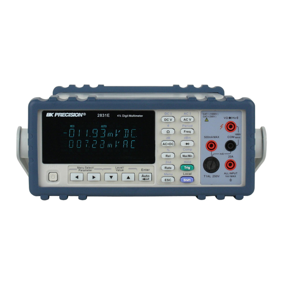
Model
2831E , 5491B
4 ½ Digit and 50,000 Count Bench
Multimeters
USER MANUAL
GlobalTestSupply
www.
.com
Find Quality Products Online at:
sales@GlobalTestSupply.com
Table of
Contents
Previous
Page
Next
Page
1
2
3
4
5
Advertisement
Table of Contents
Need help?
Do you have a question about the 2831E and is the answer not in the manual?
Ask a question
Questions and answers
Related Manuals for BK Precision 2831E
Measuring Instruments BK Precision 2530B Manual
(11 pages)
Measuring Instruments BK Precision 2650 Instruction Manual
Handheld spectrum analyzers 3.3ghz and 8.5 ghz series (76 pages)
Measuring Instruments BK Precision 2650 Instruction Manual
3.3ghz spectrum analyzer (60 pages)
Measuring Instruments BK Precision 2708B Operating Instructions
Digital multimeter (5 pages)
Measuring Instruments BK Precision 2652A User Manual
2650a/2651 series 3.3 ghz/8.5 ghz spectrum analyzer (90 pages)
Measuring Instruments BK Precision 2650A User Manual
2650a/2651 series 3.3 ghz/8.5 ghz spectrum analyzer (90 pages)
Measuring Instruments BK Precision 2658A User Manual
2650a/2651 series 3.3 ghz/8.5 ghz spectrum analyzer (90 pages)
Measuring Instruments BK Precision 2831C Lnstruction Manual
3 1/2 digit bench type digital multimeter (21 pages)
Measuring Instruments BK Precision 240A Instruction Manual
Remote network cable analyzer (5 pages)
Measuring Instruments BK Precision 2640 User Manual
2.0ghz rf field strength analyzer (84 pages)
Measuring Instruments BK Precision 2841 User Manual
Dc resistance meter (76 pages)
Measuring Instruments BK Precision 467 Service Manual
Cathode ray tube restorer/analyzer (11 pages)
Measuring Instruments BK Precision 830C Instruction Manual
Dual display capacitance meter (113 pages)
Measuring Instruments BK Precision 309 Instruction Manual
Digital earth resistance meter (9 pages)
Measuring Instruments BK Precision 8540 Instruction Manual
60v/30a/150w dc electronic load (23 pages)
Measuring Instruments BK Precision 603B User Manual
Battery capacity analyzer (42 pages)
This manual is also suitable for:
5491b
Table of Contents
Save PDF
Print
Rename the bookmark
Delete bookmark?
Delete from my manuals?
Login
Sign In
OR
Sign in with Facebook
Sign in with Google
Upload manual
Upload from disk
Upload from URL


Need help?
Do you have a question about the 2831E and is the answer not in the manual?
Questions and answers