Table of Contents
Advertisement
Quick Links
Advertisement
Table of Contents
Troubleshooting

Related Manuals for BK Precision 5335B


Summary of Contents for BK Precision 5335B
- Page 1 5335B Power Meter User Manual...
- Page 2 Safety Summary The following safety precautions apply to both operating and maintenance personnel and must be followed during all phases of operation, service, and repair of this instrument. Before applying power to this instrument: • Read and understand the safety and operational information in this manual. •...
- Page 3 Do not use this instrument in an electrical environment with a higher category rating than what is specified in this manual for this instrument. You must ensure that each accessory you use with this instrument has a category rating equal to or higher than the instrument’s category rating to maintain the instrument’s category rating.
- Page 4 • In air temperatures exceeding the specified operating temperatures. • In atmospheric pressures outside the specified altitude limits or where the surrounding gas is not air. • In environments with restricted cooling air flow, even if the air temperatures are within specifications. •...
- Page 5 known-operating voltage sources and test for both DC and AC voltages. Do not attempt any service or adjustment unless another person capable of rendering first aid and resuscitation is present. Do not insert any object into an instrument’s ventilation openings or other openings. Hazardous voltages may be present in unexpected locations in circuitry being tested when a fault condition in the circuit exists.
- Page 6 Safety Symbols DANGER indicates a hazardous situation which, if not avoided, will result in death or serious injury. WARNING indicates a hazardous situation which, if not avoided, could result in death or serious injury CAUTION indicates a hazardous situation which, if not avoided, will result in minor or moderate injury A Caution.
-
Page 7: Table Of Contents
Contents Contents 1 General Information 1.1 Features ..........1.2 Front Panel . - Page 8 CONTENTS 6 Waveform Display Function 6.0.1 Trigger Status ......... 6.1 Trigger Setup .
-
Page 9: General Information
Chapter 1 General Information Note: The contents of this manual and included specifications are subject to change go to for the latest version. The BK5335B power meter measures AC and DC inputs up to 600Vrms and 20Arms from DC to 100kHz. It measures voltage, current, power, frequency, power factor, phase and harmonic parameters up to the 50th order. -
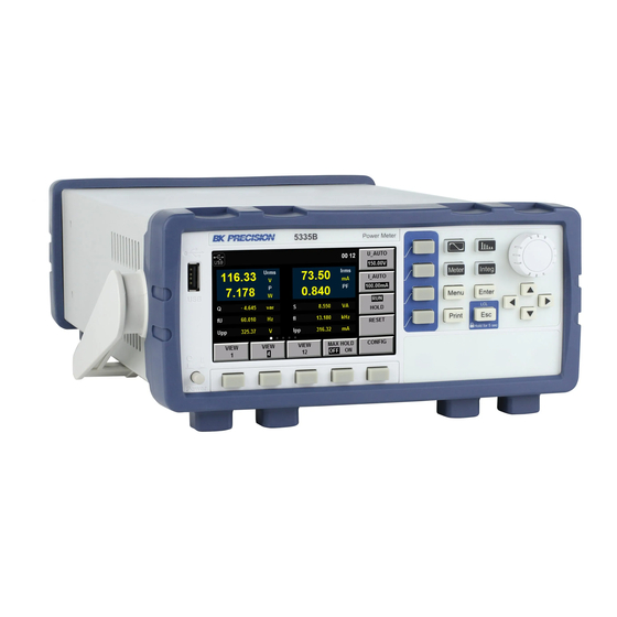
Page 10: Front Panel
CHAPTER 1. GENERAL INFORMATION 1.2 Front Panel Figure 1.1: Front Panel Power Button Rotary Knob 4.3” LCD Arrow Keys Soft-keys Main Functions Soft-keys Menu, Enter, ESC Print (Screen Capture) Name and function Waveform Display key: press to view waveforms. See Chapter Harmonic Measurement key: For viewing harmonic measurements. -
Page 11: Rear Panel Summary
CHAPTER 1. GENERAL INFORMATION 1.3 Rear Panel Summary Figure 1.2: Rear View GPIB Connector AC Line LAN Connector External Current Sensor USB Connector Voltage Input RS-232 Connector Current Shunt Input Synchronization BNC 1.4 Power Line Connection Input power requirements: AC Voltage 110V ±10% or 220V ±10% Frequency 47Hz –... -
Page 12: Power-Up Sequence
CHAPTER 1. GENERAL INFORMATION Model Fuse Specification (110V) Fuse Specification (220V) 5335B T 10A, 250 V T 6.3A, 250V Table 1.1: Required Fuses Figure 1.3: Fuse Holder 2. Locate the fuse box in the rear panel, beneath the AC power socket. Figure 3. -
Page 13: Menu
Chapter 2 Menu Configuration of system-wide settings is done from the “Menu”. Pressing the button enters the configuration/system menu, Figure 2.1. From the main menu, the soft-keys at the bottom of the screen provide access to the configuration screens. See Table 2.1 MENU >... -
Page 14: Communication Configuration Menu
2.1.2 Communication Configuration Menu Available remote interfaces are RS-232, USBTMC, GPIB and LAN. For details about commands and use of the remote interfaces, see the programming manual. The manual is found on the product page of the 5335B at www.bkprecision.com 2.1.2.1 RS-232... - Page 15 CHAPTER 2. MENU Figure 2.3: COMM Configuration - RS-232 Figure 2.4: COMM Configuration - USB 2.1.2.2 USB This unit operates as a USBTMC (USB Test and Measurement Class) device. There are no configuration options for this interface. Figure 2.1.2.3 GPIB The GPIB interface may be configured to addresses 1 through 30.
-
Page 16: System Configuration Menu
CHAPTER 2. MENU Figure 2.5: COMM Configuration - GPIB Figure 2.6: COMM Configuration - LAN (DHCP) 2.1.2.4 LAN The LAN (Ethernet) interface may be configured as either DHCP or static. Use the arrow keys to select the IP Mode field. When DHCP is selected, the current IP, subnet, and gateway are shown on screen (Figure 2.6). When “MANU”... -
Page 17: Self Test
CHAPTER 2. MENU Figure 2.7: COMM Configuration - LAN (Manual (static)) Figure 2.8: System Config Menu 2.1.4 Self Test The unit has a built in self test. This function tests the LEDs, the screen and some of the internal electronics, Figure 2.9. -
Page 18: Menu > Setup Menus
CHAPTER 2. MENU Figure 2.9: System Self Test Figure 2.10: System Initialize Menu 2.2 MENU > SETUP menus From the “MENU” function, the next page is the “SETUP” soft-key (Figure 2.11). This screen essentially gives a summary of the settings controlling measurements. 2.2.1 Averaging Setup When measuring low frequency signals where measurements begin to become unstable, averaging may be useful. - Page 19 CHAPTER 2. MENU Field Description Average Listing of the average mode settings. Sync Source The measurement synchronization signal source. Line Filter The state of the line filter. Update rate How often to measure Freq Filter The state of the frequency filter. Crest Factor The Crest Factor setting state ExSensor1...
-
Page 20: External Sensor Setup
CHAPTER 2. MENU State The state of the average function, On or Off. Type Exp or Line. Exp enables index averaging, and Line enables linear averaging. Tcontrol Sets averaging to being either a rolling of repeating average. Count EXP averaging attenuation constant, or LINE average count. 2.2.1.1 EXP - Index averaging (2.1) Dn The value displayed after the nth index averaging (D1, the value displayed after the first averaging, is equal... -
Page 21: Inrush Measurement Setup
The crest factor is the ratio of the waveform peak to the effective value. The Measurement Conditions crest factor of 5335B is specified as the times of the crest value which can be input under the rated input conditions. The crest factor CF3 or CF6 can be selected in the interface “Menu > SETUP > OTHER SET”. See Chapter for more details. - Page 22 CHAPTER 2. MENU Field Description Select the synchronization source: U/I/OFF. The overall interval of Sync Source the signal voltage, current or data updating cycle can be selected as the synchronization source for measurement. Set the status of the frequency filter. When “ON” is selected, the Freq Filter frequency filter is turned on.
-
Page 23: Cal Zero
CHAPTER 2. MENU Field Description State ON/OFF - Enable or disable inrush measurement. Trig Level(A) The current level to triggin inrush measurement Delay Time(ms) The hold off time following a trigger to start measurement Measure Time(s) The duration of the measurement following trigger and delay 2.3 CAL ZERO Perform a zero calibration of the unit. - Page 24 CHAPTER 2. MENU...
-
Page 25: External Current Sensor
Chapter 3 External Current Sensor More information to be added in future versions of this documentation. When using an external current sensor, the power meter has more current range options. Sensor Input Crest Factor Ranges EXT1 Crest Factor 3 (CF=3) 2.5 V, 5 V, 10 V EXT1 Crest Factor 6 (CF=6) -
Page 26: Measurement Setup
Chapter 4 Measurement Setup Central to setting the proper range of the instrument is the Crest Factor. Crest factor is the ratio of the peak value of a waveform to the RMS value of the waveform. For example, a perfect sine wave crest factor RMS value is 0.707*Peak. -
Page 27: Voltage And Current Range
CHAPTER 4. MEASUREMENT SETUP 1. In the “Meter” interface Press the soft key corresponding to either “U-RANGE” or “A-RANGE”, and use the knob or the arrow keys to select the voltage or current range desired. See Table 2. Press the “Enter” key to confirm the setting. Otherwise the instrument will automatically confirm and exit the setting after 5 seconds of no activity. -
Page 28: Measurement Interval
CHAPTER 4. MEASUREMENT SETUP 4.2 Measurement interval The measurement interval is the time during which data is taken. The fundamental frequency of the measured signals restricts the measurement intervals that yield meaningful results. For example, measuring 10Hz with an interval of less than the 0.5s setting will not yield stable results. The unit needs a number of cycles to be present to determine the frequency, and measurement intervals are not synchronized to the input. -
Page 29: Filter
CHAPTER 4. MEASUREMENT SETUP Figure 4.2: Measurement Timing 2 Function Description Synchronization Source, the source used to determine the measure- Sync Source ment interval. May be set to voltage (U), current (I) or turned off. Freq Filter Enable or disable the Frequency Filter. Line Filter Enable or disable the Line Filter. -
Page 30: Averaging Function
CHAPTER 4. MEASUREMENT SETUP Line filter It is inserted in the voltage and current measurement circuit and has direct influence on measurement of the voltage, current and power. When the line filter is switched on, noise and high-frequency components from the inverter or distortion waveform can be filtered. The cutoff frequency is 500Hz. 4.4 Averaging Function ⇒... -
Page 31: Linear Averaging
CHAPTER 4. MEASUREMENT SETUP The value displayed after the nth index averaging, (D , the value displayed after the first averaging, is equal to M1) The value displayed after the (n-1)th index averaging the nth measured data. attenuation constant (1-64) 4.4.2 Linear averaging + . -
Page 32: Meter Display
Chapter 5 Meter Display The 5335B has 3 configurable display formats. Each format also allows for 5 different configured sets of measurement. 1 large and 6 small, 4 large and 6 small, or 12 small measurements may be displayed. See Figures 5.1, 5.2, 5.3. - Page 33 CHAPTER 5. METER DISPLAY Figure 5.1: 1 main measurement Figure 5.2: 4 main measurements...
- Page 34 CHAPTER 5. METER DISPLAY Figure 5.3: 12 main measurements...
-
Page 35: Waveform Display Function
Chapter 6 Waveform Display Function The 5335B power meter displays waveform representations of the sampled data measured. This function is designed to be similar to an oscilloscope with many of the typical functions of oscilloscopes available, like trigger, run/stop and single trigger. The capture of data is not limited to that displayed onscreen, the measurement interval is also involved. -
Page 36: Trigger Setup
CHAPTER 6. WAVEFORM DISPLAY FUNCTION Parameter name Parameter descriptions V_RANGE Voltage range setting: press to set the voltage range A_RANGE Current range setting: press to set the current range RUN/STOP Run/stop: press to run or stop waveform capture Single measurement: pressing this stops capture and proceeds with a single capture SINGLE of data following a trigger event. -
Page 37: External Trigger Input (Ext)
CHAPTER 6. WAVEFORM DISPLAY FUNCTION Mode trigger mode Slope trigger slope 6.1.1 External trigger input (Ext) When the trigger source is set as Ext, input the trigger signal into the external signal input interface (Synchronous) of the rear panel according to the following specifications. Projects Specification Interface type... -
Page 38: Harmonic Measurement Function
Chapter 7 Harmonic Measurement Function With the 100kHz bandwidth, the 5335B power meter can realize harmonic measurement of high speed and wide dynamic range. The voltage, current, active power, reactive power, phase of harmonics and total harmonic distortion (THD) factor can be tested in harmonic measurement mode. Display of harmonic parameters is either in list or bar chart form for clear analysis of test results. -
Page 39: List Mode
CHAPTER 7. HARMONIC MEASUREMENT FUNCTION Figure 7.1: Bar graph mode - Harmonics Figure 7.2: Selecting Specific Harmonics 7.2 List Mode Enter this mode by pressing the button (if not in the harmonic mode already), then select “LIST” from the on-screen soft-keys. This list is used for showing the voltage, current, active power, reactive power, phase and total harmonic distortion (THD) factor of different harmonics. - Page 40 CHAPTER 7. HARMONIC MEASUREMENT FUNCTION Figure 7.3: List mode - Harmonics Abbreviations Instruction U(V) Voltage I(mA) Current P(mW) Power Q(mvar) Reactive Power S(mVA) Apparent Power PF() Power Factor ◦ Phase difference of k-order harmonic voltage and harmonic current ϕUI( ◦ Phase difference of harmonic voltage U(k) and fundamental U(1) ϕUU( ◦...
-
Page 41: Setup Menu
7.3.2 Distortion factor Distortion is either calculated relative to the fundamental (%f) or to the total signal (%r). Internally, the 5335B calculates according to the following equations:... -
Page 42: Pll Source
PLL source automatically, at most 50. 7.3.3 PLL source In the harmonic mode, 5335B uses a PLL to multiply the input signal fundamental. The frequency multiplication is used as the A/D sampling clock in the instrument in order to achieve ideally synchronous sampling. - Page 43 CHAPTER 7. HARMONIC MEASUREMENT FUNCTION time is approximately more than or equal to 150ms (data measurement interval and data processing time). Therefore, select the data update rate of 250ms or more for measurement and display of harmonic data.
-
Page 44: Integral Operation Function
(sold) or consuming (buying) directions. The 5335B power meter can be used for integral operation of the current and power of the input unit. Technical indicators can be calculated. In addition, the range can be switched automatically in the Buy and Sell modes according to the input level so as to accurately complete integrate measurement. -
Page 45: Introduction Of Soft Keys On The Interface
CHAPTER 8. INTEGRAL OPERATION FUNCTION Figure 8.2: Meter Display Parameter name Parameter descriptions Voltage range setting: press the soft key corresponding to this parameter to set V_RANGE the voltage range. Current range setting: press the soft key corresponding to this parameter to set A_RANGE the current range. -
Page 46: Integral Measurement Display Information
CHAPTER 8. INTEGRAL OPERATION FUNCTION Character Function description Display the integral start and stop mode. Start mode: MANUAL and TIME Mode Stop mode: MANUAL, TIME and TINTerval. State Display the current status of the integral function. Start displayed when the integral function is working. Stop displayed when the integral function is interrupted, canceled or stopped. -
Page 47: Setting Of Integral Measurement Configuration
CHAPTER 8. INTEGRAL OPERATION FUNCTION Current integral Integral interrup- Function Integral resetting status tion Wiring Executable Unenforceable Unenforceable Measurement range Executable Unenforceable Unenforceable Filter Executable Unenforceable Unenforceable Averaging function Executable Unenforceable Unenforceable Synchronization Executable Unenforceable Unenforceable Data updating rate Executable Unenforceable Unenforceable Integral mode... -
Page 48: Parameter Descriptions
CHAPTER 8. INTEGRAL OPERATION FUNCTION 1. Press “Integ” to enter the integral measurement interface. 2. Press the soft key corresponding to the “SETUP” parameter in the integral measurement interface to enter the integral parameter configuration interface. 8.4.1 Parameter descriptions: Start set in the MANUAL mode or TIME mode via the right soft key. MANUAL press the “START”... -
Page 49: Integration
CHAPTER 8. INTEGRAL OPERATION FUNCTION 8.5 Integration When the integral measurement function is enabled, you can keep the current integral information and carry out the following operations: exit, start and stop. Specific steps are as follows: Operation steps 1. Press “Integ” to enter the integral display interface. 2. -
Page 50: Remote Operation
Chapter 9 Remote Operation There are four types of communication interfaces available:USB,Ethernet,GPIB and RS232.You can choose any one of them to communicate with a PC. 9.1 RS-232 Interface RS232 interface:use a cable with two COM interface (DB9) to connect power meter and PC. It can be activated by menu key on the front panel.All SCPI commands are available through RS-232 programming. -
Page 51: Rs-232 Communication Settings
CHAPTER 9. REMOTE OPERATION Pin # Signal Table 9.1: RS-232 (DE-9) Pinout Note that the eledtronic load is configured for 1 start bit and 1stop bit (these values are fixed). The correct interface cables or adapters must be used, as described under RS-232 connector. Note that even if the cable has the proper connectors for your system,the internal wiring may be incorrect. -
Page 52: Gpib Interface
(IP address, subnet mask and default gateway) to PCs and other equipment connected to the network. 5335B cannot use DHCP unless the network is provided with a DHCP server. Please ask your network administrator DHCP if DHCP is available. - Page 53 CHAPTER 9. REMOTE OPERATION • The default gateway controls data exchange between networks and protocols to ensure smooth data transmission. • Ask your network administrator about values of default gateway. It is possible that the setting is unnecessary. Use DHCP network to automatically set the default gateway.
-
Page 54: Specifications
Chapter 10 Specifications The specifications listed below are valid and specified for the following conditions: • Warm up time of 30 minutes ◦ • Ambient temperature - 23 ± 5 • Relative humidity 30 to 75%... - Page 55 Power Meter 5335B Specifications Specifications are subject to the following conditions Temperature: 23±5° C, humidity: 30 to 75% RH. Warm-up time: 30 minutes Model 5335B General Measurement Specifications Peak to peak, Maximum, Minimum, Average_rms, Average_rectified, DC, Voltage, Current Crest factor (current), Inrush (current)
- Page 56 Power Meter 5335B Specifications (cont.) Current Measurement Accuracy and Ranges CF= 3:5 mA, 10 mA, 20 mA, 50 mA, 100 mA, 200 mA, 0.5 A, 1 A, 2 A, 5 A, 10 A, 20 A Direct input range CF= 6:2.5 mA, 5 mA, 10 mA, 25 mA, 50 mA, 100 mA, 250 mA, 0.5 A, 1 A, 2.5 A, 5 A, 10 A CF = 3: 2.5 V, 5 V, 10 V...
- Page 57 Power Meter 5335B Specifications (cont.) Harmonic Measurement Parameters Measurement method PLL synchronization Frequency range PLL frequency source range 10 Hz to 1.2 kHz (typical) FFT data length 1024 Window function Rectangle Fundamental frequency (Fund. freq.) 10 Hz to 75 Hz...
-
Page 58: Routine Maintenance
Instrument” of 5335B Installation Instructions for detailed steps of self-inspection. 11.2 Error Information References The 5335B power meter has a detailed error and prompt information function, so as to help the user to easily carry out positioning and measurement during measurement and use. This section describes all error information of the 5335B power meter as well as error causes and disposals. - Page 59 CHAPTER 11. ROUTINE MAINTENANCE Error information Error information explanation Error description The start time is less than the current time. Start time is less than cur- Possible cause The integral setting is incorrect. rent Disposal Reset the integral start time. Error description The ending time is less than the current time.
-
Page 60: Daily Maintenance
CHAPTER 11. ROUTINE MAINTENANCE Error information Error information explanation Error description The oscilloscope function cannot be enabled. Scope openfail Possible cause Communication abnormality Disposal Check the communication cable. Error description Time setting fails. Time set fail Possible cause Time setting is illegal. Disposal Reset the system time. -
Page 61: Troubleshooting
CHAPTER 11. ROUTINE MAINTENANCE Prompt information Explanation of prompt information Cal Zero is working! The instrument is calibrating the zero point. Cal Zero is completed! The instrument has completed zero point calibration. Test screen Self-inspection of LCD screen Test dsp Self-inspection of DSP. - Page 62 CHAPTER 11. ROUTINE MAINTENANCE • Check whether the instrument displays error information. • Use other instruments instead of this instrument for confirmation.
-
Page 63: Limited Three-Year Warranty
Chapter 12 LIMITED THREE-YEAR WARRANTY B&K Precision Corp. warrants to the original purchaser that its products and the component parts thereof, will be free from defects in workmanship and materials for a period of three years from date of purchase. B&K Precision Corp. -
Page 64: Service Information
Chapter 13 Service Information Warranty Service: Please go to the support and service section on our website at bkprecision.com to obtain an RMA #. Return the product in the original packaging with proof of purchase to the address below. Clearly state on the RMA the performance problem and return any leads, probes, connectors and accessories that you are using with the device.
Need help?
Do you have a question about the 5335B and is the answer not in the manual?
Questions and answers