
Subscribe to Our Youtube Channel
Related Manuals for BK Precision 875B


Summary of Contents for BK Precision 875B
- Page 1 Instruction Manual MANUAL DE INSTRUCCIÓNES Model 875B Digital LCR Meter Medidor Digital LCR Modelo 875B...
-
Page 2: Table Of Contents
ONE: INTRODUCTION Inspection Included Items Unit Descriptions TWO: OPTERATION AND MEASUREMENT Warning Cautions 875B Zero Adjustment and Impedance Measurement 2.3.1 Zero Adjustment and Capacitance Measurement 2.3.2 Zero Adjustment and Inductance Measurement 2.3.3 Resistance Measurement Measurement Parameter Conversions THREE: SPECIFICATIONS Power Source... -
Page 3: Inspection
Congratulations! You ha ve just pur chased some of t he mo st advanced hand-held digital LCR meter available. This meter is sure to provide years of reliable service. The 875B is designed to m easure the param eters of an impedance e lement w ith high accuracy and speed. -
Page 4: Unit Descriptions
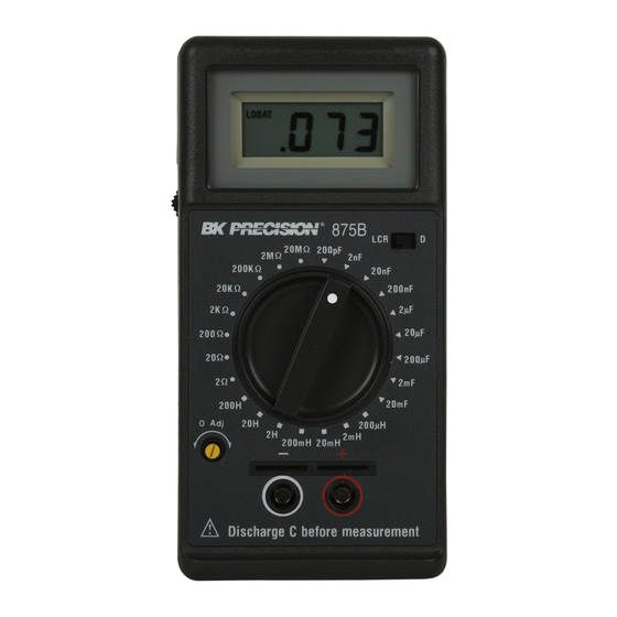
Unit Description Please use the dr awings of the 87 5B, in co njunction with the following descriptions of the con trols and co nnections to help familiarize you with the unit: (1) Liquid Crystal Display : Indicates the value of capacitance connected to the test inputs. -
Page 5: Warning
TWO: OPERATION AND MEASUREMENT Warning Electricity can cause severe injur ies or even d eath, sometimes even with relatively low voltages or currents. Therefore it is vitally important that any electronic instruments such as these meters be totally understood before use. Please do not use this instrume nt, or any other piece of electrical or electr onic test e quipment, w ithout f irst th oroughly familiarizin g yourself with its correct operation and use. -
Page 6: 875B Zero Adjustment And Impedance Measurement
875B Zero Adjustments and Impedance Measurements IMPORTANT INFORMATION: 1. As an added feature, the 875B has +/- offsets. The +/-offsets allow for measurements when the LCD is not at zero. The +/- offsets are applicable to components that are measured in the following modes: capacitor para llel (Cp), inductor series (Ls) and resistance series (Rs). -
Page 7: Measurement
(6) Set the m eter to p roper capacitance range and go to step seven to measure capacitance. 20µF, 200µF, 2mF & 20mF (Cs): Range Zero Adjustment (Cs Mode) (4) Set the capacitance meter to the 2µF Capacitance range. (5) Using a small, flat-blade screwdriver, slowly turn the “0 Adj” control to calibrate the display for a zero re ading. -
Page 8: Zero Adjustment And Inductance
WCsRs w here C s in th e mea sured va lue and R s is measured by 2Ω range. NOTE: To avoid possible damage to the instrument, discharge all capacitors before attemp ting to measure the va lue or dissipation factor. -
Page 9: Resistance Measurement
2H, 20H, 200H, range (Lp): Zero Adjustment & Measurements (1) Set the power switch to “on” position. (2) Set the mode switch to the “LCR” position. NOTE: These three ranges (Lp mode) must be zero calibrated at 200mH range. (3) Set the Function/Range switch to the 200mH range. (4) Using a short piece of w ire, such as a paper clip, temporarily connect the po sitive and nega tive m easurement terminals together. -
Page 10: Measurement Parameter Conversions
(1) Turn unit on. (2) Set the mode switch to the “LCR” position. (3) Set the Function/Range switch to the appropriate resistance range. If the value of resistance is unknown, select the 2 ohm range. (4) Using a short piece of w ire, such as a paper clip, temporarily connect the po sitive and nega tive m easurement terminals together. -
Page 11: Three: Specifications
series mode capacitance of 1250pF. Cs=( 1 + D × D ) × Cp Cs=( 1 + 0.5 × 0.5 ) × 1000pF Cs=1250pF E.G.2: With a me asurement frequency of 1K Hz, a series inductance of 1000uH with a dissipation factor of 0.5 has a series resistance of 3.14 ohms. -
Page 13: Instrument Specifications
INSTRUMENT SPECIFICATIONS Electrical Specifications (See tables 2) NOTE: (1) The test leads should be as short as possible to minimize the measurement error. For best accuracy, zero adjustment should be performed appropriately before testing. Table 2. CAPACITANCE Range *Accuracy Resolution Test Condition 200pF 0.1pF... - Page 14 π Series Mode fCsRs RESISTANCE Range Accuracy Resolution Test Condition 2Ω 1%+5 1mΩ 10mArms Series 20Ω 10mΩ 10mArms Mode 200Ω 100mΩ 1mArms 1KHz 1%+2 2KΩ 1Ω 0.1mArms 20KΩ 10Ω 10µArms 200KΩ 100Ω 1µArms 2MΩ 1KΩ Parallel Mode 2%+2 1KHz, 0.5Vrms 20MΩ...
-
Page 15: General Specifications
DISSIPATION FACTOR Range Accuracy Lx≦200mH 200mH<Lx<200H 0 ~ 1.999 2000 2000 Accuracy is ± ( % of reading+number of digits ). Lx is inductance readout in counts. Accuracy is applied when L is from 20 to 100% of full scale range in parallel mode measurements. -
Page 16: Four: Useer Maintenance
FOUR: USER MAINTENANCE Battery Replacement When the instrument displays the “LO BAT” ind ication, the battery must be replaced t o maintain proper operation. Please perform the following steps to change the battery: (1) Remove the battery hatch by sliding it towards the bottom of the instrument. - Page 17 Limited Three-Year Warranty B&K Precision Corp. warrants to the original purchaser that its products and the component parts thereof, will be free from defects in workmanship and materials for a period of three years from date of purchase. B&K Precision Corp. will, without charge, repair or replace, at its option, defective product or component parts.
-
Page 18: Service Information
Service Information Warranty Service: Please return the product in the original packaging with proof of purchase to the address below. Clearly state in writing the performance problem and return any leads, probes, connectors and accessories that you are using with the device. - Page 19 MANUAL DE INSTRUCCIÓNES Medidor Digital LCR Modelo 875B...
- Page 20 INDICE UNO: INTRODUCCION 1.1 Inspección 1.2 Partes incluidas 1.3 Descripción de la unidad DOS: OPERACIÓN Y MEDICIONES 2.1 Advertencia 2.2 Precauciones 2.3 Ajuste de cero y medición de impedancia 2.3.1Ajuste de cero y medición de capacitancia 2.3.2 Ajuste de cero y medición de inductancia 2.3.3 Medición de resistencia 2.4 Conversiones de parámetros de...
- Page 21 Medidor Plomos de prueba (1 par) Batería Descripción de la unidad Por favor, use los diagramas del 875B junto con la descripción de los controles e indicadores siguiente para ayudarlo a familiarizarse con la unidad: Pantalla de cristal líquido : Indica el valor de la capacitancia...
- Page 22 Switch de Función/Rango : Selecciona la función y rango para la medición deseada Terminal común : Conector negativo (común) para todas las mediciones Terminal positiva : Conector positivo (alto) para todas las mediciones Jack de terminal común : Jack tipo banana negativo (bajo) para mediciones que requieren puntas de prueba Jack de terminal positiva...
- Page 23 Ajuste de cero y mediciones de impedancia INFORMACION IMPORTANTE El 875B incluye desplazamientos +/-. Estos desplazamientos permiten la medición ciando el LCD no está en cero. Los desplazamientos son aplicables para componentes que se miden en los modos siguientes: Cp (capacitor en paralelo), Ls (inductor serie), y Rs (resistencia serie).
- Page 24 Fije el switch de función/rango en el rango de capacitancia apropiado. Si desconoce el valor del capacitor, seleccione el rango de 200pF NOTA: Si usa las puntas de prueba, insértelas en los jacks tipo banana, pero no las conecte. Rango 200pF, 2nF, 20nF, 200nF & 2µF (Cp); modo de ajuste de cero (modo Cp) +Fije el medidor de capacitancia al rango seleccionado Rote lentamente el control “0 Adj”...
- Page 25 La resistencia serie equivalente es usualmente mucho mayor que la resistencia óhmica serial de las puntas y envoltura de un capacitor, pues incluye también el efecto de pérdida dieléctrica. ESR se relaciona con D mediante la fórmula ESR = Rs = D/wCs (w representa “omega”...
- Page 26 Rangos 2H, 20H (Lp); ajuste de cero & mediciones Fije el switch de encendido en la posición “ON” Fije el switch de modo en la posición “LCR” NOTA: Estos 3 rangos (modo Lp) deben calibrarse en el rango de 200mH Fije el switch de función/rango en el rango de inductancia de 200mH Use un trozo pequeño de alambre, como un clip de papel, para...
- Page 27 Use un trozo pequeño de alambre, como un clip de papel, para conectar en corto las terminales positiva y negativa. Si las puntas del clip se usan para la medición,insértelas en los jacks banana y conéctelas juntas. Rote lentamente el control “0 Adj” con un desarmador pequeño plano para mostrar cero en pantalla.
- Page 29 TRES: ESPECIFICACIONES Fuente de poder Tipo de batería: 006P de 9V Consumo de batería: 155mW Especificaciones del instrumento Especificaciones eléctricas (Vea las tablas 2) NOTA: (1) Las puntas de prueba deben ser tan cortas como sea posible para minimizar errores del Instrumento (2) Para la mejor precisión, ajuste el cero correctamente antes de la prueba.
- Page 30 La precisión es ±(% de lectura + número de dígitos) Cx es la lectura de la capacitancia en cuentas La precisión se aplica cuando Cx es del 20 al 100% de la escala completa del rango en modo de medición serial Modo paralelo π...
- Page 31 INDUCTANCIA Rango Precision Resolucion Condicion de prueba 200µH 2%+2 0.1µH 10mArms, 1KHz Modo 1µH 10mArms, 1KHz Serial 1%+2 20mH 10µH 1mArms, 1KHz 200mH 100µH 0.1mArms,1KHz Modo Paralelo 10mH 120Hz, 0.5Vrms Specified* 200H 100mH La precisión es ±(% de lectura + número de dígitos) y se aplica del 10 al 100% de la escala completa en mediciones de modo paralelo FACTOR DE DISIPACION Rango...
- Page 32 NOTA: LA PRECISION TOTAL SE GARANTIZA A TEMPERATURAS DE 15°C a 28°C Y MEDIO AÑO DE CICLO DE CALIBRACION ESPECIFICACIONES GENERALES Energía Batería sencilla de 9V 006P Pantalla Altura de 0.5”, digital, 3 ½ LEDS con anunciadores “LO BAT” y decimal Advertencia de Indicador en pantalla muestra “LO BAT”...
- Page 33 CUATRO: MANTENIMIENTO POR EL USUARIO 4.1 Reemplazo de batería Cuando el instrumento exhibe “LO BAT” es preciso reemplazar la batería para una operación adecuada. Siga los pasos siguientes: Remueva el receptáculo de la batería deslizándolo hacia el fondo del instrumento Libere la batería vieja del sujetador.
- Page 34 Garantía Limitada de Tres Anos B&K Precision Corp. Autorizaciones al comprador original que su productos y componentes serán libre de defectos por el periodo de tres anos desde el día en que se compro. B&K Precision Corp. sin carga, repararemos o sustituir, a nuestra opción, producto defectivo o componentes.
- Page 35 Información de Servicio Servicio de Garantía: Por favor regrese el producto en el empaquetado original con prueba de la fecha de la compra a la dirección debajo. Indique claramente el problema en escritura, incluya todos los accesorios que se estan usado con el equipo. Servicio de No Garantía: Por favor regrese el producto en el empaquetado original con prueba de la fecha de la compra a la dirección debajo.
-
Page 36: Ec Declaration Of Conformity
Manufacture’s Address : 22820 Savi Ranch Parkway Yorba Linda, CA 92887. Modification : The 875B is not designed for use with a AC to DC adaptor, only Just enough use with 9V 006P Battery. (please cancel item 3.1 on Page9 of operation manual). - Page 37 22820 Savi Ranch Parkway Yorba Linda, California 92887 U.S.A. Tel. 714.921.9095 Fax. 714.921.6422 P/N: 480-796-9-001...
Need help?
Do you have a question about the 875B and is the answer not in the manual?
Questions and answers