Sign In
Upload
Download
Table of Contents
Contents
Add to my manuals
Delete from my manuals
Share
URL of this page:
HTML Link:
Bookmark this page
Add
Manual will be automatically added to "My Manuals"
Print this page
×
Bookmark added
×
Added to my manuals
Manuals
Brands
BK Precision Manuals
Measuring Instruments
879B
Instruction manual
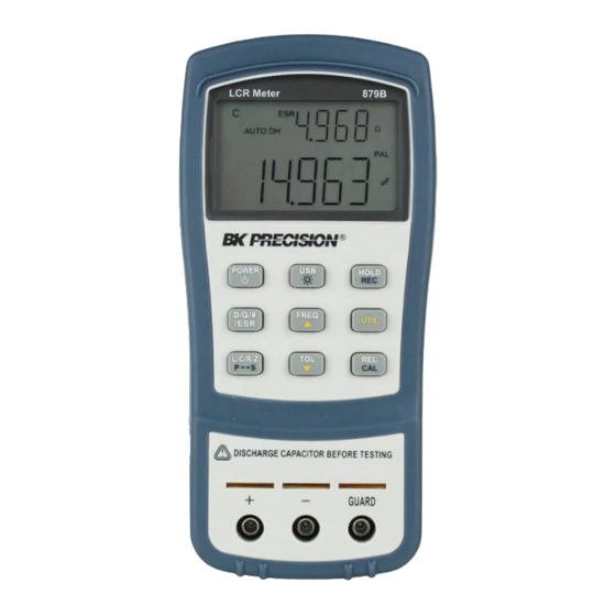
BK Precision 879B Instruction Manual
Dual display lcr meter
Hide thumbs
Also See for 879B
:
Instruction manual
(142 pages)
1
2
3
4
5
6
7
8
Table Of Contents
9
10
11
12
13
14
15
16
17
18
19
20
21
22
23
24
25
26
27
28
29
30
31
32
33
34
35
36
37
38
39
40
41
42
43
44
45
46
47
48
49
50
51
52
53
54
55
56
57
58
59
60
61
62
63
64
65
66
67
68
69
70
71
72
73
74
75
76
77
78
79
80
81
82
83
84
85
86
87
88
89
90
91
92
93
94
95
96
97
98
99
100
101
102
103
104
105
106
107
108
109
110
111
112
113
114
115
116
117
118
119
120
121
122
123
124
125
126
127
128
129
130
131
132
133
134
135
136
137
138
139
140
141
142
page
of
142
Go
/
142
Contents
Table of Contents
Bookmarks
Table of Contents
Safety Summary
Safety Guidelines
Compliance Statements
Table of Contents
Introduction
Package Contents
Front Panel Overview
Front Panel Display Descriptions
Front Panel Buttons
Lcd Display Overview
LCD Display Descriptions
Special Display Indicators
Powering Instrument
Installing Battery
Connecting External Power Source
Low Battery Indication
Backlit Display (Model 879B Only)
Operation Instructions
Data Hold
Static Recording
L/C/R/Z Select Mode
D/Q/Θ/Esr Select Mode
Test Frequency
Relative Mode
Tolerance
Utility Menu
Parallel and Series Measurement Mode
Calibration
Usb
Automatic Fuse Detection
Quick Start Guide
Caution
Inductance Measurement
Capacitance Measurement
Resistance Measurement
Impedance Measurement (Model 879B Only)
Remote Communication
Connecting Instrument to PC
USB (Virtual COM) Configuration
USB Operation
Command Protocols
Supplemental Information
Selecting Test Frequency
Selecting Series or Parallel Mode
Accuracy Discrepancies
Guard Terminal
Specifications
General Specifications
Accuracy Specifications
Maintenance
Service
Cleaning
Service Information
Limited Warranty
Advertisement
Quick Links
1
L/C/R/Z Select Mode
2
Calibration
3
Capacitance Measurement
Download this manual
Model
Dual Display LCR
METER
INSTRUCTION MANUAL
878B, 879B
Table of
Contents
Previous
Page
Next
Page
1
2
3
4
5
Advertisement
Table of Contents
Need help?
Do you have a question about the 879B and is the answer not in the manual?
Ask a question
Questions and answers
Related Manuals for BK Precision 879B
Measuring Instruments BK Precision 878B Instruction Manual
Dual display lcr meter (142 pages)
Measuring Instruments BK Precision 875B Instruction Manual
Digital lcr meter (37 pages)
Measuring Instruments BK Precision 880 Instruction Manual
Dual display lcr (71 pages)
Measuring Instruments BK Precision 830C Instruction Manual
Dual display capacitance meter (113 pages)
Measuring Instruments BK Precision 890C Instruction Manual
Dual display capacitance meter (113 pages)
Measuring Instruments BK Precision 8540 Instruction Manual
60v/30a/150w dc electronic load (23 pages)
Measuring Instruments BK Precision 894 User Manual
500 khz/1 mhz lcr meter (112 pages)
Measuring Instruments BK Precision 895 User Manual
500 khz/1 mhz lcr meter (112 pages)
Measuring Instruments BK Precision 8500B Series User Manual
Programmable dc electronic loads (77 pages)
Measuring Instruments BK Precision 889B Manual
(30 pages)
Measuring Instruments BK Precision 830B Manual
(59 pages)
Measuring Instruments BK Precision 890B Manual
(59 pages)
Measuring Instruments BK Precision 8550 Series User Manual
Programmable вс electronic loads (58 pages)
Measuring Instruments BK Precision 8551 User Manual
Programmable вс electronic loads (58 pages)
Measuring Instruments BK Precision 885 Operating Manual
Lcr meter (91 pages)
Measuring Instruments BK Precision 310 Instruction Manual
Digital milli-ohm meter (20 pages)
This manual is also suitable for:
878b
Bk880
Bk878b
Bk879b
Table of Contents
Save PDF
Print
Rename the bookmark
Delete bookmark?
Delete from my manuals?
Login
Sign In
OR
Sign in with Facebook
Sign in with Google
Upload manual
Upload from disk
Upload from URL


Need help?
Do you have a question about the 879B and is the answer not in the manual?
Questions and answers