BK Precision 8500B Series User Manual
Programmable dc electronic loads
Hide thumbs
Also See for 8500B Series:
- User manual (56 pages) ,
- Programming manual (63 pages) ,
- User manual (58 pages)
Table of Contents
Advertisement
Quick Links
Advertisement
Table of Contents

Related Manuals for BK Precision 8500B Series


Summary of Contents for BK Precision 8500B Series
-
Page 2: Table Of Contents
Contents Compliance Information EMC ................5 IEC Measurement Category &... - Page 3 6.1.5 CR Mode ..............6.1.6 CW Mode .
- Page 4 Configuration Menu Navigating the Configuration Menu ..........Protect .
-
Page 5: Compliance Information
Compliance Information 1.1 EMC EC Declaration of Conformity - EMC Compliance was demonstrated to the following specifications listed in the Official Journal of the European Communities: EMC Directive 2014/30/EU. EN 61010-1:2010 Safety requirements for electrical equipment for measurement, control, and laboratory use Part 1: General requirements... -
Page 6: Iec Measurement Category & Pollution Degree Definitions
Compliance Information 1.2 IEC Measurement Category & Pollution Degree Definitions Measurement Category (CAT) - classification of testing and measuring circuits according to the types of mains circuits to which they are intended to be connected. Measurement Category other than II, III, or IV : circuits that are not directly connected to the mains supply. -
Page 7: Product End-Of-Life Handling
Compliance Information 1.3 Product End-of-Life Handling The equipment may contain substances that could be harmful to the environment or human health if improperly handled at the product’s end of life. To avoid release of such substances into the environment and to reduce the use of natural resources, we encourage you to recycle this product to an appropriate system that will ensure that most of the materials are reused or recycled appropriately. - Page 8 Compliance Information Symbols - HIGH VOLTAGE - possibility of electric shock. WARNING – Statements or instructions that must be consulted in CAUTION order to find out the nature of the potential hazard and any actions which must be taken. On (Supply). This is the AC mains connect/disconnect switch on the front of the instrument.
-
Page 9: Safety Notices
Safety Notices The following safety precautions apply to both operating and maintenance personnel and must be followed during all phases of operation, service, and repair of this instrument. Before applying power to this instrument: • Read and understand the safety and operational information in this manual. •... - Page 10 Safety Notices Ground the Instrument To minimize shock hazard, the instrument chassis and cabinet must be connected to an electrical safety ground. This instrument is grounded through the ground conductor of the supplied, three- conductor AC line power cable. The power cable must be plugged into an approved three-conductor electrical outlet.
- Page 11 Safety Notices Environmental Conditions This instrument is intended to be used in an indoor pollution degree 2 environment. The operating temperature range is 0 C to 40 C and 20% to 80% relative humidity, with no condensation allowed. ∘ ∘ Measurements made by this instrument may be outside specifications if the instrument is used in non- office-type environments.
- Page 12 Safety Notices Do not operate instrument if damaged If the instrument is damaged, appears to be damaged, or if any liquid, chemical, or other material gets on or inside the instrument, remove the instrument’s power cord, remove the instrument from service, label it as not to be operated, and return the instrument to B&K Precision for repair.
- Page 13 Safety Notices Do not touch live circuits Instrument covers must not be removed by operating personnel. Component replacement and internal adjustments must be made by qualified service-trained maintenance personnel who are aware of the hazards involved when the instrument’s covers and shields are removed.
- Page 14 Safety Notices Servicing Do not substitute parts that are not approved by B&K Precision or modify this instrument. Return the instrument to B&K Precision for service and repair to ensure that safety and performance features are maintained. Fuse replacement must be done by qualified service-trained maintenance personnel who are aware of the instrument’s fuse requirements and safe replacement procedures.
-
Page 15: General Information
General Information 3.1 Product Overview The 8500B Series DC Electronic Loads are versatile instruments used for static and dynamic testing of DC power supplies, batteries, DC-to-DC converters, battery chargers, and other applications including fuel-cell, and solar cell test. Primary modes include constant voltage (CV), constant current (CC), constant resistance (CR), and constant power (CW). -
Page 16: Features
Report any damage to the shipping agent immediately. Save the original packing carton for possible future reshipment. Every instrument is shipped with the following contents: • 8500B series DC Electronic load • IT-E132B USB to TTL adapter • AC Power Cord •... - Page 17 General Information Verify that all items above are included in the shipping container. If anything is missing, please contact B&K Precision.
-
Page 18: Product Dimensions
General Information 3.4 Product Dimensions All models are designed to fit in a standard 19-inch rackmount. The dimensions are shown in table 3.2. Model Dimensions (W x H x D) Weight 8542B 8500B 8.5” x 3.5” x 14” (214.5 x 88.2 x 354.6 mm) 10.3 lbs (4.7 kg) 8502B 8510B... -
Page 19: Front Panel Overview
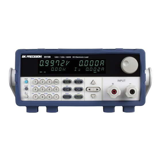
General Information 3.6 Front Panel Overview Figure 3.3 Front Panel Item Name Description Display Vacuum Fluorescent Display Power Button Toggles the instrument ON or OFF. Used to enter precise values and call advanced Numeric Keypad functions. Function Keys section 5.1.1 for details. -
Page 20: Combination Keys
General Information 3.6.1 Combination Keys Press button first and then other keys to activate the more advanced functions. Turn short circuit on or off. Start or stop transient condition. Set LIST operation parameters. Store the DC Load state in non-volatile memory. Turn on or off battery testing function. -
Page 21: Rear Panel Overview
General Information 3.7 Rear Panel Overview Figure 3.4 Rear Panel Overview Item Name Description AC power input Houses the fuse as well as the AC input. & fuse box Line Voltage Selection Select 110/220V±10%AC input. Connect an external voltmeter or oscilloscope to Current Monitoring display the input’s current. -
Page 22: Display Overview
General Information 3.8 Display Overview Figure 3.5 Display Overview Item Description Measured Voltage Measured Current Measured Power Set Value Input Off indicator, lit when input is off Operation mode indicators (CC, CV, CW, CR) Remote control active indicator Error indicator Waiting for Trigger indicator Timer indicator External indicator... -
Page 23: Getting Started
Getting Started Before connecting and powering up the instrument, please review the instructions in this chapter. 4.1 Input Power and Fuse Requirements The load has a selectable AC input that accepts line voltage input within: 8542B | 8500B | 8502B | 8510B 8514B AC Line Input 115 V (... -
Page 24: Fuse Requirements And Replacements
Getting Started 4.2 Fuse Requirements and Replacements An AC input fuse is necessary when powering the instrument. All models in the HVL series require a Time delay low breaking capacity 5A/250V (T 5A L 250V). For safety, no power should be applied to the instrument while changing line voltage operation. -
Page 25: Input Connection
Getting Started 4.3 Input Connection It is recommended to use the proper wire and lug for the load wiring. The following factors are needed to take into consideration: • Insulation rating of the wire • Current carrying capacity of the wire •... -
Page 26: Noise And Impedance Effects
Getting Started 4.3.2 Noise and Impedance Effects To minimize noise pickup or radiation interference, use a shielded pair wiring or the shortest possible length for load wires. Connect the shield to the chassis via a rear panel mounting screw. If shielding is impossible or impractical, simply twisting the wires together will offer some noise immunity. When using local sense connections, the user must use the largest practical wire size to minimize the effects of load line impedance on the regulation of the load. -
Page 27: Local/Remote Sense
Getting Started 4.4 Local/Remote Sense The electronic load is capable of sensing voltage locally or remotely. If the load wiring is relatively short and the load regulation is not critical, local sense configuration is good enough. On the other hand, if the load wiring is relatively long, configuring to remote sense will compensate for the voltage drop of the long load leads. -
Page 28: Preliminary Check
Getting Started 4.5 Preliminary Check Complete the following steps to verify the Power supply is ready for use. Verify AC Input Voltage Verify and check to make sure proper AC voltages are available to power the instrument. The AC voltage range must meet the acceptable specification as explained in section “2.1 Input Power and Fuse Requirements”. - Page 29 Getting Started If the load is not drawing power from the DC power supply, check all load protection limits and settings within the menu to verify that the load is configured to allow drawing power at 5V, 0.500 A. Also, verify that the CC mode parameters are setup to operate within the configured valid ranges by pressing If after checking all of the above, and verifying the power supply used for testing is not at fault, contact B&K for further assistance.
-
Page 30: Front Panel Operation
5.1 Keys 5.1.1 Function Keys The 8500B series is equipped with six function keys. Figure 5.1 Function Keys , and buttons change the operation mode of the load to the corresponding mode. -
Page 31: Numeric Keys And Esc
Front Panel Operation 5.1.2 Numeric Keys and ESC Figure 5.2 Numeric Keys The numeric keys allow for the configuration of the currently selected parameter. Using the numeric keys provides a fast and precise input. Pressing the Enter key will assign the selected value to the desired parameter. -
Page 32: Operation Modes
Operation Modes The 8500B series offers the following modes. Static Modes .............. -
Page 33: Static Modes
300 W 10 mV 600 W 0.1 to 18 V 1500 W Range range for all operation modes and models in the 8500B series. Input voltage High 0.25 V at 3 A 0 to 150 V 0.1 to 150 V 0.14 V at 3 A... -
Page 34: Slew Rate Configuration
Programmable DC Electronic Loads or as fast as 1 A/µs depending on the model and selected current range as shown in table 6.2. Range 8500B Series High 10 Ω to 7.5 kΩ 10 Ω to 7.5 kΩ 10 Ω to 7.5 kΩ... -
Page 35: Constant Current Mode (Cc)
Operation Modes 6.1.3 Constant Current Mode (CC) In constant current mode, the load will sink a current in accordance with the programmed value regardless of the input voltage. Figure 6.1 Constant Current Mode To run the CC operation RUNMODE must be set to Normal and CC must be selected by pressing the button. -
Page 36: Cv Mode
Operation Modes 6.1.4 CV Mode In constant voltage mode the load will sink enough current to control the DUT voltage to the programmed value. The load acts as a shunt voltage regulator when operating in CV mode. Figure 6.2 Constant Voltage Mode To run the CV operation RUNMODE must be set to Normal and CV must be selected by pressing the button. -
Page 37: Cr Mode
Operation Modes 6.1.5 CR Mode In constant resistance mode the load will sink a current linearly proportional to the voltage in accordance with the programmed resistance value to approximate a resistor. The performance of this mode is not as fast as in CC or CV mode. This is because it is a sampled system and response to changing input takes a finite amount of time. -
Page 38: Cw Mode
Operation Modes 6.1.6 CW Mode In constant power mode the load will maintain the input power at the specified programmed power level. When input voltage increases, the input current will decrease, while power (P = V*I) will remain the same. This is a sampled system, so the performance is not as fast as in CC and CV modes. -
Page 39: Short Mode
Operation Modes 6.1.7 Short Mode Short mode simulates a short-circuit at the input. In short mode, the DC load will draw the maximum current from the source. The short function is available in any of the four operation modes (CC,CV,CW or CR). -
Page 40: Transient Operation
1 mV Resolution 6.2 Transient Operation High 10 mV ±(0.05% + 0.02% FS) Accuracy High ±(0.05% + 0.025% FS) The 8500b series provides 3 transient testing modes: CC mode • • • Continuous Pulse Toggle 0 to 3 A 0 to 3 A... -
Page 41: Continuous Transient Mode
Operation Modes 6.2.1 Continuous Transient Mode A continuous transient generates a respective pulse stream that toggles between two load levels. Upon receiving a trigger the load will continuously switch between the A/B levels preset as shown in Figure 6.2.1. Figure 6.5 Continuous Transient Mode Freq/Period The period value represents the time it takes for a periodic waveform to complete one full cycle or repetition. -
Page 42: Configure Continuous Transient Mode
Operation Modes A/B Level The A/B Level refers to the two values the transient function will transition between. The values units will vary depending on the selected Load Mode. 6.2.2 Configure Continuous Transient Mode To configure and run the Continuous Transient operation: Step 1. -
Page 43: Pulse Transient Mode
Operation Modes 6.2.3 Pulse Transient Mode In pulse transient operation, the electronic load generates a pulse with user-defined amplitude and width when a trigger signal is received. Figure 6.6 Pulse Transient Mode Pulse Width The pulse width value refers to the duration or length of time that a pulse remains on the specified level. Pulse width is measured is specified in ms. -
Page 44: Configure Pulse Transient Mode
Operation Modes 6.2.4 Configure Pulse Transient Mode To configure and run the Pulse Transient operation: Step 1. Select the desired Static Mode. Step 2. Press the buttons to enter the Transient Configuration menu. Step 3. Use the right and left navigation keys to set TRAN to "ON", then press the to confirm... -
Page 45: Toggle Transient Mode
Operation Modes 6.2.5 Toggle Transient Mode In toggle transient operation the electronic load will switch between the main level and the transient level when a trigger signal is received. The load will remain at the transient level until another trigger is received, at which time the load will switch back from the transient level to the main level. -
Page 46: Configure Toggle Transient Mode
Operation Modes 6.2.6 Configure Toggle Transient Mode To configure and run the Pulse Transient operation: Step 1. Select the desired Static Mode. Step 2. Press the buttons to enter the Transient Configuration menu. Step 3. Use the right and left navigation keys to set TRAN to "ON", then press the to confirm... -
Page 47: List Mode
Operation Modes 6.3 List Mode List mode allows users to generate complex sequences of input changes with rapid, precise timing, which may be synchronized with internal or external signals. The internal memory has the capacity to save up to 7 list files, with each file capable of storing up to 84 steps. -
Page 48: Create/Edit A List File
Operation Modes 6.3.1 Create/Edit a List File List mode consist of two portions List Setup and List Configuration. To setup up list mode follow the steps below: Step 1. Press the buttons to enter the LIST menu. Step 2. Use the right and left navigation keys to select EDI, then press the In order to edit a file List mode must be disabled. -
Page 49: Run List
Operation Modes 6.3.2 Run List To run a previously saved list file: Step 1. Press the buttons to enter the LIST menu. Step 2. Use the right and left navigation keys to select CALL, then press the Step 3. Use the numeric keypad to set the RECALL LIST. -
Page 50: Battery Mode
Operation Modes 6.4 Battery Mode The battery test function of our DC load offers comprehensive assessment capabilities for battery performance through the use of the constant current operation. The process involves configuring the test mode and specifying discharge stop conditions. For our product line, three distinct discharge stop conditions can be set. -
Page 51: Run Battery Test
Operation Modes 6.4.2 Run Battery Test To run the battery test operation RUNMODE must be set to BATTERY and CC must be selected by pressing the button. For more information about RUNMODE please refer to section RUNMODE. To run a previously saved battery test profile: Step 1. -
Page 52: Program Test
Operation Modes 6.5 Program Test The Program Test feature comprises Test files, offering a broader scope than lists. These files enable the creation of test sequences, incorporating various modes, mode parameters, and durations. They prove instrumental in executing a series of tests on a device and subsequently indicating whether each test passed or failed. -
Page 53: Program Test Configuration
Operation Modes 6.5.1 Program Test Configuration The 8550B series is capable of storing up to 10 Program Test profiles. To configure a program test file: Step 1. Press the button to enter the Program Test menu. Step 2. Use the numeric keypad to activate the desired steps. - Page 54 Operation Modes Step 5. Use the to set the parameters of each step. numeric keypad • SEQ<n> ON: Specifies the input on time of the step. Press the to confirm the value. • SEQ<n> OFF: Specifies the input off time of the step. Press the to confirm the value.
-
Page 55: Run A Program Test
Operation Modes • Use the to set the LOW value. Press the to confirm the lower limit numeric keypad for the program test step. • Use the numeric keypad to set the UP value. Press the to confirm the rise time for the program test step. -
Page 56: Ocp Test Mode
Operation Modes 6.6 OCP Test Mode OCP Test Process: Once the input voltage reaches the VON point, the DC load initiates drawing current from the source after a delay time. The current value incrementally rises at regular intervals. Concurrently, the DC load assesses whether the input voltage is below the set OCP voltage. If it is, the current value is then compared to determine if it falls within the specified current range. - Page 57 Operation Modes Step 8. Use the to set the current END value. Press the to confirm the current numeric keypad value that will terminate the test. Step 9. Use the numeric keypad to set the OCP VOLT value. Press the to confirm the voltage stop condition.
-
Page 58: Run An Ocp Test
Operation Modes 6.6.2 Run an OCP Test Once you have configured the OCP test, proceed to follow the steps below. Step 1. Press the to enter the System menu. Step 2. Use the navigation keys to select the RUNMODE submenu. Press the to enter the RUNMODE submenu. -
Page 59: Opp Test Mode
Operation Modes 6.7 OPP Test Mode OPP Test Process: Once the input voltage reaches the VON point, power activation will commence following a specified delay. The power level will increment at regular intervals. Concurrently, the DC load assesses whether the input voltage falls below the designated OPP voltage. If the voltage is below the OPP threshold, the current value is then scrutinized to determine if it aligns with the predefined current range. - Page 60 Operation Modes Step 7. Use the to set the STEP DEL. Press the to confirm the delay time to numeric keypad hold each step. This dictates the speed at which the test will progress through each step. Step 8. Use the numeric keypad to set the power END value.
-
Page 61: Run An Opp Test
Operation Modes 6.7.2 Run an OPP Test Once you have configured the OPP test, proceed to follow the steps below. Step 1. Press the to enter the System menu. Step 2. Use the navigation keys to select the RUNMODE submenu. Press the to enter the RUNMODE submenu. -
Page 62: Led Test Mode
Operation Modes 6.9 LED Test Mode The Constant Resistance LED mode approximates a diode characteristic by configuring two main parameters: the overall resistance and the diode threshold voltage (Vd). When the input voltage surpasses the threshold (Vd), the load’s resistance decreases. For instance, by setting Vd to 1.6 V, R to 0.1, and connecting to a current-limited power supply with voltage limit set to 5 V and current limit to 300 mA, activating the input results in an input voltage of approximately 1.6 V and a current of 300 mA. -
Page 63: System Menu
System Menu Navigating the System Menu ............POWER-ON . -
Page 64: Navigating The System Menu
System Menu 7.1 Navigating the System Menu To effectively navigate the menu and optimize your experience with the instrument, familiarize yourself with its menu structure and understand how to view or modify settings and parameters. Follow these steps for seamless navigation: Step 1. -
Page 65: Knob
System Menu 7.4 Knob The knob setting allows the user to configure the auto save of parameter’s adjustment when the rotary knob is used. UPDATE The adjusted value using the knob during operation will be retained/saved even after the load is turned off. For instance, if the DC load is initially set to 1 A, and then increased to 2 A using the knob, the modified setting will persist even after turning off the load, once powered again, the setting value will remain at 2 A. -
Page 66: Memory
System Menu 7.6 MEMORY The instrument has the capability to store up to 100 settings in its non-volatile memory. This memory is organized into 10 storage groups (group 0 to 9), with each group having 10 memory locations (0 to 9) for storing settings. -
Page 67: Display
System Menu 7.7 DISPLAY The instrument features an internal timer that monitors the duration of the enabled (ON) input. Enables the timer. The timer will replace the input measurement shown on the display below the voltage measurement. Figure 7.1 Timer Disabled Disables the timer. -
Page 68: Address
System Menu 7.10 ADDRESS Sets the instrument’s communication address (0-31). For successful communication, it is essential that the communication address in the DC load aligns with the computer software; otherwise, communication will not be established. 7.11 RUNMODE Sets the instruments operation mode. The instrument supports 5 modes: •... -
Page 69: Configuration Menu
Configuration Menu Navigating the Configuration Menu ..........Protect . -
Page 70: Navigating The Configuration Menu
To effectively navigate the menu and optimize your experience with the instrument, familiarize yourself Programmable DC Electronic Loads 8500B Series with its menu structure and understand how to view or modify settings and parameters. Follow these steps for seamless navigation: Specifications (continued) Step 1. -
Page 71: A-Limit
Configuration Menu 8.2.2 A-LIMIT A-Limit limits the maximum current that can flow through the load. When the current exceeds the set threshold, the load shuts down to prevent damage to the load or the power source. OCP is crucial for preventing excessive current that could lead to overheating, component failure, or unsafe conditions. -
Page 72: Measure
Configuration Menu 8.3 MEASURE The MEASURE settings comprise parameters specifically crafted to customize the process of capturing voltage measurements. These settings encompass the voltage range, filter count, and voltage thresholds for calculation of the voltage rise/fall time. 8.3.1 V-RANGE The V-RANGE parameter enables/disables the auto voltage range function on a DC load. When enabled the load will automatically adjusts the voltage range based on the applied load, ensuring optimal and precise voltage measurements without manual intervention. -
Page 73: Von
Configuration Menu 8.5 VON VON safeguards an electronic system under test, preventing power application unless the supply voltage surpasses a specific threshold. It is crucial not to arbitrarily set this value if there is no specific testing requirement. In cases where the instrument is unable to function normally, such as when setting CC=1 A and the current remains at 0 A after turning on the input, it is advisable to check the VON set initially. -
Page 74: Specifications
Specifications Programmable DC Electronic Loads 8500B Series Specifications Note: All specifications apply to the unit after a temperature stabilization time of 30 minutes over an ambient temperature range of 23 °C ± 5 °C. Model 8542B 8500B 8502B 8510B 8514B... - Page 75 Programmable DC Electronic Loads 8500B Series Specifications Specifications (continued) Model 8542B 8500B 8502B 8510B 8514B Readback voltage 0 to 18 V 0 to 50 V 0 to 18 V Range High 0 to 150 V 0 to 500 V 0 to 120 V 0.1 mV...
-
Page 76: Service Information
Service Information Warranty Service: Please go to the support and service section on our website at bkprecision.com to obtain an RMA #. Return the product in the original packaging with proof of purchase to the address below. Clearly state on the RMA the performance problem and return any leads, probes, connectors and accessories that you are using with the device. -
Page 77: Limited Three-Year Warranty
LIMITED THREE-YEAR WARRANTY B&K Precision Corp. warrants to the original purchaser that its products and the component parts thereof, will be free from defects in workmanship and materials for a period of three years from date of purchase. B&K Precision Corp. will, without charge, repair or replace, at its option, defective product or component parts.
Need help?
Do you have a question about the 8500B Series and is the answer not in the manual?
Questions and answers