
Related Manuals for Vega VEGACAP 35


Summary of Contents for Vega VEGACAP 35
- Page 1 Operating Instructions Capacitive cable electrode for level detection VEGACAP 35 Relay (DPDT) Document ID: 33759...
-
Page 2: Table Of Contents
How to proceed if a repair is necessary ................26 Dismount..........................27 Dismounting steps......................27 Disposal ......................... 27 Supplement ..........................28 Technical data ........................ 28 Dimensions ........................32 Industrial property rights ....................33 Trademark ........................33 Editing status: 2023-04-26 VEGACAP 35 • Relay (DPDT) -
Page 3: About This Document
Symbols used Document ID This symbol on the front page of this instruction refers to the Docu- ment ID. By entering the Document ID on www.vega.com you will reach the document download. Information, note, tip: This symbol indicates helpful additional infor- mation and tips for successful work. -
Page 4: For Your Safety
During work on and with the device, the required personal protective equipment must always be worn. Appropriate use The VEGACAP 35 is a sensor for point level detection. You can find detailed information about the area of application in chapter " Product description". Operational reliability is ensured only if the instrument is properly used according to the specifications in the operating instructions manual as well as possible supplementary instructions. -
Page 5: Conformity
That is why we have introduced an environment management system with the goal of continuously improving company environmental pro- tection. The environment management system is certified according to DIN EN ISO 14001. Please help us fulfil this obligation by observing the environmental instructions in this manual: • Chapter " Packaging, transport and storage" • Chapter " Disposal" VEGACAP 35 • Relay (DPDT) -
Page 6: Product Description
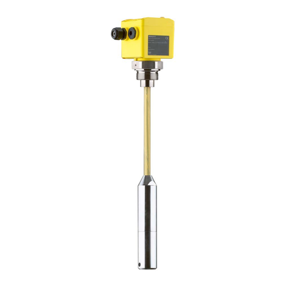
– If necessary, further certificates Information: Optional instrument features are also described in this operating instructions manual. The respective scope of delivery results from the order specification. Constituent parts The VEGACAP 35 consists of the components: • Process fitting with probe • Housing with electronics • Housing lid Fig. -
Page 7: Principle Of Operation
The capacitance change is converted by the electronics module into a switching command. Voltage supply VEGACAP 35 is a compact instrument, i.e. it can be operated without external evaluation system. The integrated electronics evaluates the level signal and outputs a switching signal. With this switching signal, a connected device can be operated directly (e.g. -
Page 8: Packaging, Transport And Storage
Technical data - Ambient conditions" • Relative moisture 20 … 85 % Lifting and carrying With instrument weights of more than 18 kg (39.68 lbs) suitable and approved equipment must be used for lifting and carrying. VEGACAP 35 • Relay (DPDT) -
Page 9: Mounting
DIN/EN/IEC/ANSI/ISA/UL/CSA 61010-1. It can be used indoors as well as outdoors. Switching point In general, VEGACAP 35 must be mounted vertically. The instrument must be mounted in such a way that the probe is at the height of the requested switching point. -
Page 10: Mounting Instructions
Mounting instructions Agitators and fluidization Due to the effects of agitators, equipment vibration or similar, the level switch can be subjected to strong lateral forces. For this reason, do not use an overly long electrode for VEGACAP 35, but check if you can mount a short level switch on the side of the vessel in horizontal position. Inflowing medium If the instrument is mounted in the filling stream, unwanted false measurement signals can be generated. - Page 11 The probe must be mounted in a way that takes the arrangement of the filling and emptying apertures into account. To compensate measurement errors caused by the material cone in cylindrical vessels, the sensor must be mounted at a distance of d/6 from the vessel wall. VEGACAP 35 • Relay (DPDT)
- Page 12 4 Mounting Fig. 5: Filling and emptying centred Fig. 6: Filling in the centre, emptying laterally VEGACAP 35 Discharge opening Filling opening VEGACAP 35 • Relay (DPDT)
- Page 13 Make sure that the max. permissible tensile load of the suspension cable is not exceeded. The danger of this happening exists particu- larly with very heavy solids and large meas. lengths. The max. permis- sible load is stated in chapter " Technical data". VEGACAP 35 • Relay (DPDT)
-
Page 14: Connecting To Power Supply
Wiring plan - single chamber housing Wiring plan We recommend connecting VEGACAP 35 in such a way that the switching circuit is open when there is a level signal, line break or failure (safe state). - Page 15 Inductive loads also result from the connection to a PLC input or output and/or in combination with long cables. It is imperative that you take measures to extinguish sparks to protect the relay contact (e.g. Z diode) or use an electronic version with transistor output. VEGACAP 35 • Relay (DPDT)
-
Page 16: Setup
Note: As a rule, always set the mode with the mode switch (5) before start- ing setup VEGACAP 35. The switching output will change if you set the mode switch (5) afterwards. This could possibly trigger other con- nected instruments or devices. - Page 17 The measuring system is immediately ready for operation. ment The switching point must no longer be set with VEGACAP 35. The probe has an active length and a screen segment. Thanks to the screen segment, the so called standing capacitance, caused by the vessel after installation of the probe, is mainly compensated.
-
Page 18: Function Table
The following table provides an overview of the switching conditions depending on the set mode and the level. Level Switching status Control lamp Mode A Overflow protec- tion (6) (7) Relay energized Mode A Overflow protec- tion (6) (7) Relay deener- gized VEGACAP 35 • Relay (DPDT) - Page 19 Switching status Control lamp Mode B Dry run protection (6) (7) Relay energized Mode B Dry run protection (6) (7) Relay deener- gized Failure of the sup- ply voltage (mode A/B) (6) (7) Relay deener- gized VEGACAP 35 • Relay (DPDT)
-
Page 20: Diagnostics And Servicing
Should these measures not be successful, please call in urgent cases 24 hour service hotline the VEGA service hotline under the phone no. +49 1805 858550. The hotline is also available outside normal working hours, seven days a week around the clock. - Page 21 Remove the electronics module. Check the resistance between the the probe two plug connections. There must no longer be a connection (high impedance). If there is still a connection, exchange the instrument or return it for repair VEGACAP 35 • Relay (DPDT)
- Page 22 In both cases, the probe must be repaired in our premises. Contact 4 against vessel The electrical connection between contact 4 and metal vessel (not the mounting boss or probe flange) should good. Measure the resist- ance value between contact 4 and vessel with an ohmmeter (range very small). • Shortcircuit (0 … 3 Ω) - optimum connection • Resistor > 3 Ω - bad connection VEGACAP 35 • Relay (DPDT)
-
Page 23: Exchanging The Electronics Module
3. Remove the housing cover 4. Loosen the screws of the terminals with a Allen wrench. 5. Pull the connection cables out of the terminals. 6. Loosen the two screws with a Torx screwdriver. VEGACAP 35 • Relay (DPDT) -
Page 24: Shortening Of The Probe
15. Carry out a fresh adjustment. See chapter " Set up, new adjust- ment". 16. Screw the housing lid back on The electronics exchange is now finished. Shortening of the probe The cable of the probe can be shortened individually. VEGACAP 35 • Relay (DPDT) - Page 25 3. Shift the upper part of the weight (1), the four O-rings (2) and the insulating sleeve (3) upward above the planned curring site. 4. Remove the insulating sleeve (6) from the locking sleeve (4). 5. Loosen the two pins (5) on the locking sleeve (4). VEGACAP 35 • Relay (DPDT)
-
Page 26: How To Proceed If A Repair Is Necessary
Clean the instrument and pack it damage-proof • Attach the completed form and, if need be, also a safety data sheet outside on the packaging • Ask the agency serving you to get the address for the return ship- ment. You can find the agency on our homepage. VEGACAP 35 • Relay (DPDT) -
Page 27: Dismount
If personal data is stored on the old device to be disposed of, delete it before disposal. If you have no way to dispose of the old instrument properly, please contact us concerning return and disposal. VEGACAP 35 • Relay (DPDT) -
Page 28: Supplement
Torque for NPT cable glands and Conduit tubes Ʋ Plastic housing max. 10 Nm (7.376 lbf ft) Ʋ Aluminium housing max. 50 Nm (36.88 lbf ft) Measuring frequency 430 kHz Output variable Output Relay output (DPDT), 2 floating change-over contacts Switching voltage Ʋ Min. 10 mV VEGACAP 35 • Relay (DPDT) - Page 29 Storage and transport temperature -40 … +80 °C (-40 … +176 °F) Process conditions Process pressure -1 … 16 bar/-100 … 1600 kPa (-14.5 … 232 psig) See following diagram Process temperature See following diagram VEGACAP 35 • Relay (DPDT)
- Page 30 16 bar (232psi) -10°C 0°C 60°C 80°C (-4°F) (32°F) (140°F) (176°F) Fig. 12: Process pressure - Process temperature - VEGACAP 35 with process fitting of 316L Process pressure Process temperature 16 bar (232psi) -30°C 0°C 60°C 80°C (-22°F) (32°F) (140°F) (176°F) Fig. 13: Process pressure - Process temperature - VEGACAP 35 with process fitting of 316Ti Process pressure Process temperature Dielectric constant ≥ 1.5 VEGACAP 35 • Relay (DPDT)
- Page 31 For that reason the associated approval documents of these instruments have to be carefully noted. They are part of the delivery or can be downloaded by entering the serial number of your instrument into the search field under www.vega.com as well as in the general download area. VEGACAP 35 • Relay (DPDT)
-
Page 32: Dimensions
ø 13,5 mm ") ø 6 mm ") ø 40 mm ") Fig. 14: VEGACAP 35, cable version with ø 6 mm, threaded version G1½ (ISO 228 T1) Sensor length, see chapter " Technical data" VEGACAP 35 • Relay (DPDT) -
Page 33: Industrial Property Rights
Les lignes de produits VEGA sont globalement protégées par des droits de propriété intellec- tuelle. Pour plus d'informations, on pourra se référer au site www.vega.com. VEGA lineas de productos están protegidas por los derechos en el campo de la propiedad indus- trial. Para mayor información revise la pagina web www.vega.com. - Page 34 Notes VEGACAP 35 • Relay (DPDT)
- Page 35 Notes VEGACAP 35 • Relay (DPDT)
- Page 36 Subject to change without prior notice © VEGA Grieshaber KG, Schiltach/Germany 2023 VEGA Grieshaber KG Am Hohenstein 113 Phone +49 7836 50-0 77761 Schiltach E-mail: info.de@vega.com...
Need help?
Do you have a question about the VEGACAP 35 and is the answer not in the manual?
Questions and answers