Vega VEGAPULS WL 61 Operating Instructions Manual
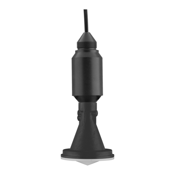
Radar sensor for continuous level
measurement of water and wastewater
Hide thumbs
Also See for VEGAPULS WL 61:
- Operating instructions manual (64 pages) ,
- Installation & maintenance instructions manual (60 pages) ,
- Quick setup manual (28 pages)

Related Manuals for Vega VEGAPULS WL 61


Summary of Contents for Vega VEGAPULS WL 61
-
Page 1: Operating Instructions
Operating Instructions Radar sensor for continuous level measurement of water and wastewater VEGAPULS WL 61 4 … 20 mA/HART - two-wire Document ID: 38061... -
Page 2: Table Of Contents
Connecting ........................27 Parameter adjustment ....................28 Setup with VEGADIS 82 Principle of operation and connection ................29 Adjustment volume ......................29 Setup steps ........................30 Setup with PC/notebook (VEGACONNECT) VEGAPULS WL 61 • 4 … 20 mA/HART - two-wire... - Page 3 13.6 Trademark ........................56 Safety instructions for Ex areas Take note of the Ex specific safety instructions for Ex applications. These instructions are attached as documents to each instrument with Ex approval and are part of the operating instructions manual. Editing status: 2017-08-23 VEGAPULS WL 61 • 4 … 20 mA/HART - two-wire...
-
Page 4: About This Document
This arrow indicates a single action. Sequence of actions Numbers set in front indicate successive steps in a procedure. Battery disposal This symbol indicates special information about the disposal of bat- teries and accumulators. VEGAPULS WL 61 • 4 … 20 mA/HART - two-wire... -
Page 5: For Your Safety
During work on and with the device the required personal protective equipment must always be worn. Appropriate use VEGAPULS WL 61 is a sensor for continuous level measurement. You can find detailed information about the area of application in chapter "Product description". Operational reliability is ensured only if the instrument is properly used according to the specifications in the operating instructions manual as well as possible supplementary instructions. -
Page 6: Eu Conformity
The instrument must be stationary mounted and the antenna directed vertically downward • The mounting location must be at least 4 km away from radio astronomy stations, unless special permission was granted by the responsible national approval authority VEGAPULS WL 61 • 4 … 20 mA/HART - two-wire... -
Page 7: Radio License For Usa/Canada
Restrictions for the USA and Canada The VEGAPULS WL 61 with wireless Bluetooth communication must neither be operated in the USA or Canada nor imported or exported. VEGAPULS WL 61 • 4 … 20 mA/HART - two-wire... -
Page 8: Installation And Operation In The Usa And Canada
That is why we have introduced an environment management system with the goal of continuously improving company environmental pro- tection. The environment management system is certified according to DIN EN ISO 14001. Please help us fulfil this obligation by observing the environmental instructions in this manual: • Chapter "Packaging, transport and storage" • Chapter "Disposal" VEGAPULS WL 61 • 4 … 20 mA/HART - two-wire... -
Page 9: Product Description
The 4-digit PIN is necessary for the Bluetooth connection to the sen- sor. The PIN is unique and is only valid of this sensor. You can find the PIN as a label on a supplementary sheet in the sen- sor packaging and next to the type label. Fig. 2: Bluetooth PIN VEGAPULS WL 61 • 4 … 20 mA/HART - two-wire... -
Page 10: Principle Of Operation
The respective scope of delivery results from the order specification. Principle of operation The radar sensor VEGAPULS WL 61 is the ideal sensor for all appli- Application area cations in the water and waste water industry. It is particularly suitable... -
Page 11: Adjustment
The determined level is converted into an appropri- ate output signal and outputted as measured value. Adjustment Adjustment via the signal cable As a standard feature, VEGAPULS WL 61 allows an adjustment via: • External display and adjustment unit VEGADIS 82 (PLICSCOM) •... -
Page 12: Packaging, Transport And Storage
Unless otherwise indicated, the packages must be stored only under the following conditions: • Not in the open • Dry and dust free VEGAPULS WL 61 • 4 … 20 mA/HART - two-wire... -
Page 13: Accessories And Replacement Parts
VEGADIS 82 is suitable for measured value indication and adjustment of sensors with HART protocol. It is looped into the 4 … 20 mA/HART signal cable. You can find further information in the operating instructions "VEGADIS 82 4 … 20 mA/HART" (Document-ID 45300). VEGAPULS WL 61 • 4 … 20 mA/HART - two-wire... -
Page 14: Mounting
Kevlar. In order to avoid faulty measured values, make sure that the sensor does not oscillate. > 200 mm (7.87") Fig. 5: Mounting via a straining clamp VEGAPULS WL 61 • 4 … 20 mA/HART - two-wire... - Page 15 Mounting strap - Ceiling mounting ceiling. This ensures swivelling of the sensor up to 180° for optimum orienta- tion. Fig. 7: Ceiling mounting via the mounting strap with length 300 mm VEGAPULS WL 61 • 4 … 20 mA/HART - two-wire...
- Page 16 Fig. 10: Wall mounting with inclined wall via the mounting strap with length 300 mm Flange mounting For mounting the instrument on a socket or a manhole cover, an unassembled combi collar flange for DN 80 (ASME 3" or JIS 80) is optionally available also as retrofitting part. VEGAPULS WL 61 • 4 … 20 mA/HART - two-wire...
-
Page 17: Mounting Preparations, Mounting Strap
The emitted radar impulses of the radar sensor are electromagnetic waves. The polarisation is the direction of the electrical wave compo- nent. By turning the instrument in the connection flange or mounting strap, the polarisation can be used to reduce the effects of false echoes. The position of the polarisation is marked by marking bars on the instrument. VEGAPULS WL 61 • 4 … 20 mA/HART - two-wire... - Page 18 Fig. 13: Mounting of the radar sensor on round vessel tops In vessels with conical bottom it can be advantageous to mount the sensor in the centre of the vessel, as measurement is then possible down to the bottom. VEGAPULS WL 61 • 4 … 20 mA/HART - two-wire...
- Page 19 Approximate values of the socket heights are shown in the following illustration. The socket end should be smooth and burr-free, if possi- ble also rounded. After mounting, you have to carry out a false signal suppression during the parameter adjustment. VEGAPULS WL 61 • 4 … 20 mA/HART - two-wire...
- Page 20 Make sure when planning your measuring point that the radar sensor has a "clear view" to the measured product. In case of existing vessel installations, a false signal suppression should be carried out during setup. VEGAPULS WL 61 • 4 … 20 mA/HART - two-wire...
- Page 21 Overflow orifice (side view) Headwater Tailwater Overfall orifice (view from tailwater) In general, the following points must be observed: • Install the sensor on the headwater side • Installation in the centre of the flume and vertical to the liquid surface • Distance to the overfall orifice VEGAPULS WL 61 • 4 … 20 mA/HART - two-wire...
- Page 22 In general, the following points must be observed: • Installation of the sensor at the inlet side • Installation in the centre of the flume and vertical to the liquid surface • Distance to the Venturi flume • Min. distance of the sensor to max. storage level VEGAPULS WL 61 • 4 … 20 mA/HART - two-wire...
-
Page 23: Connecting To Power Supply
Wiring plan Wire assignment, con- nection cable Fig. 21: Wire assignment in permanently connected connection cable Brown (+) and blue (-) to power supply or to the processing system Shielding VEGAPULS WL 61 • 4 … 20 mA/HART - two-wire... -
Page 24: Switch-On Phase
As soon as a plausible measured value is found, the corresponding current is outputted to the signal cable. The value corresponds to the actual level as well as the settings already carried out, e.g. factory setting. VEGAPULS WL 61 • 4 … 20 mA/HART - two-wire... -
Page 25: Setup With Smartphone/Tablet (Bluetooth)
• Operating system: Android 4.3 or newer • Bluetooth Smart from 4.0 Download the app "VEGA Tools" from the Apple App Store or Google Play Store to your smartphone or tablet. Connecting Connecting … Start the "VEGA Tools" app and select the function "Setup". The smartphone/tablet searches automatically for Bluetooth-capable instruments in the area. -
Page 26: Sensor Parameter Adjustment
The selected menu item, recognisable by the colour change, is dis- played in the right half. Fig. 23: Example of an app view - Setup sensor adjustment Enter the requested parameters and confirm via the keyboard or the editing field. The settings are then active in the sensor. Close the app to terminate connection. VEGAPULS WL 61 • 4 … 20 mA/HART - two-wire... -
Page 27: Setup With Pc/Notebook (Bluetooth)
A supplementary sheet in the sensor packaging Note: If an incorrect sensor PIN is entered, the PIN can only be entered again after a delay time. This time gets longer after each incorrect entry. VEGAPULS WL 61 • 4 … 20 mA/HART - two-wire... -
Page 28: Parameter Adjustment
DTMs are compiled in a DTM Collec- tion. The DTMs can also be integrated into other frame applications according to FDT standard. Fig. 25: Example of a DTM view - Setup, sensor adjustment VEGAPULS WL 61 • 4 … 20 mA/HART - two-wire... -
Page 29: Setup With Vegadis
Setup: Settings, for example, for medium, application, vessel form, adjustment, signal output Diagnosis: Information, for example on the instrument status, peak value, reliability, echo curve memory as well as simulation VEGAPULS WL 61 • 4 … 20 mA/HART - two-wire... -
Page 30: Setup Steps
8 Setup with VEGADIS 82 Additional adjustment: False signal suppression, linearization, reset Info: Instrument type and serial number Setup steps You can find a detailed description of the setup steps for VEGAPULS WL 61 in the operating instructions manual "VEGADIS 82 - 4 … 20 mA/HART". VEGAPULS WL 61 • 4 … 20 mA/HART - two-wire... -
Page 31: Setup With Pc/Notebook (Vegaconnect)
VEGADIS 82 VEGADIS 82. Parameter adjustment options: • VEGADIS 82 • Sensor Fig. 27: Connection of the PC via interface adapter USB cable to the PC Interface adapter VEGACONNECT VEGADIS 82 VEGAPULS WL 61 • 4 … 20 mA/HART - two-wire... - Page 32 149A, VEGAMET 381, VEGAMET 391. Common Ex separators are also usually equipped with a sufficient current limiting resistance. In such cases, the interface converter can be connected parallel to the 4 … 20 mA cable (dashed line in the previous illustration). VEGAPULS WL 61 • 4 … 20 mA/HART - two-wire...
-
Page 33: Parameter Adjustment
"DTM Collection/PACTware" attached to each DTM Collection and which can also be downloaded from the Internet. Detailed descrip- tions are available in the online help of PACTware and the DTMs. VEGAPULS WL 61 • 4 … 20 mA/HART - two-wire... -
Page 34: Saving The Parameterisation Data
CD from the agency serving you. Saving the parameterisation data We recommend documenting or saving the parameterisation data via PACTware. That way the data are available for multiple use or service purposes. VEGAPULS WL 61 • 4 … 20 mA/HART - two-wire... -
Page 35: Set Up With Other Systems
This software is updated via the Internet and new EDDs are automatically accepted into the device catalogue of this software after they are released by the manufacturer. They can then be transferred to a Field Communicator. VEGAPULS WL 61 • 4 … 20 mA/HART - two-wire... -
Page 36: Diagnosis, Asset Management And Service
Changes in the measure- ment conditions during operation or buildup on the sensor can thus be recognized. The echo curve of the setup is stored via: • PC with PACTware/DTM • Control system with EDD • Display and adjustment module VEGAPULS WL 61 • 4 … 20 mA/HART - two-wire... -
Page 37: Asset Management Function
Plan in maintenance for the instrument because a failure is expected in the near future (e.g. due to buildup). This status message is inactive by default. It can be activated by the user via PACTware/DTM or EDD. VEGAPULS WL 61 • 4 … 20 mA/HART - two-wire... - Page 38 The following table shows the error codes and text messages in the Failure status message "Failure" and gives information on the cause and how to eliminate it. Keep in mind that some specifications are only valid for four-wire instruments and the electronics of VEGAPULS WL 61 can- not be exchanged by the user. Code Cause...
- Page 39 • • M502 Hardware error EEPROM Exchanging the electronics Bit 2 of • Send instrument for repair Byte 14 … 24 Error in the diag- nostics memory VEGAPULS WL 61 • 4 … 20 mA/HART - two-wire...
-
Page 40: Rectify Faults
• • Current signal greater than Electronics module in the Exchange the instrument or send it in for repair 22 mA or less than 3.6 mA sensor defective VEGAPULS WL 61 • 4 … 20 mA/HART - two-wire... - Page 41 Determine the reason for the signal has changed (e.g. con- changed false signals, carry out densation, buildup); false signal false signal suppression, e.g. suppression no longer matches with condensation actual conditions VEGAPULS WL 61 • 4 … 20 mA/HART - two-wire...
- Page 42 The antenna • sensor goes into overfill protec- Use a sensor with a more suit- time tion mode. The max. level (0 m able antenna distance) as well as the status message "Overfill protection" are outputted. VEGAPULS WL 61 • 4 … 20 mA/HART - two-wire...
-
Page 43: Software Update
24 hour service hotline Should these measures not be successful, please call in urgent cases the VEGA service hotline under the phone no. +49 1805 858550. The hotline is also available outside normal working hours, seven days a week around the clock. -
Page 44: How To Proceed If A Repair Is Necessary
Attach the completed form and, if need be, also a safety data sheet outside on the packaging • Please contact the agency serving you to get the address for the return shipment. You can find the agency on our home page www.vega.com. VEGAPULS WL 61 • 4 … 20 mA/HART - two-wire... -
Page 45: Dismount
Pass the instrument directly on to a spe- cialised recycling company and do not use the municipal collecting points. These may be used only for privately used products according to the WEEE directive. VEGAPULS WL 61 • 4 … 20 mA/HART - two-wire... -
Page 46: Supplement
Measured variable The measured quantity is the distance between the end of the sensor antenna and the product surface. The reference plane for the measurement is the lower side of the flange. VEGAPULS WL 61 • 4 … 20 mA/HART - two-wire... - Page 47 Ʋ TV (Third Value) Lin. percent Ʋ QV (Fourth Value) Scaled Fulfilled HART specification Further information on Manufacturer ID, See website of HART Communication Foundation Device ID, Device Revision Default values can be assigned individually. VEGAPULS WL 61 • 4 … 20 mA/HART - two-wire...
- Page 48 Ʋ Non-Ex and Ex-ia version < ±15 µA Deviation in the current output due to < ±150 µA strong, high-frequency electromagnetic fields acc. to EN 61326 Characteristics and performance data Measuring frequency K-band (26 GHz technology) Measuring cycle time approx. 450 ms VEGAPULS WL 61 • 4 … 20 mA/HART - two-wire...
-
Page 49: Ambient Conditions
Ʋ Wire isolating and cable cover Ʋ Colour Black Ʋ Fire protection classification UL94-V0 Connection cable, electrical data Ʋ Wire cross-section 0.5 mm² (AWG 20) Time span after a sudden distance change of max. 0.5 m until the output signal reaches for the first time 90% of the final value (IEC 61298-2). Outside the specified beam angle, the energy level of the radar signal is 50% (-3 dB) less. EIRP: Equivalent Isotropic Radiated Power VEGAPULS WL 61 • 4 … 20 mA/HART - two-wire... - Page 50 = 24 V DC Potential connections and electrical separating measures in the instrument Electronics Not non-floating Ground terminal Galvanically connected with the metal process fitting Galvanic separation between electronics and metal housing parts Ʋ Reference voltage 500 V AC VEGAPULS WL 61 • 4 … 20 mA/HART - two-wire...
-
Page 51: Radio Astronomy Stations
Instruments with approvals can have different technical specifications depending on the version. For that reason the associated approval documents of these instruments have to be carefully noted. They are part of the delivery or can be downloaded under www.vega.com, "Instrument search (serial number)" as well as in the download area. 13.2 Radio astronomy stations Certain requirements for the use outside closed vessels result from the radio license for Europe of VEGAPULS WL 61. You can find the requirements in chapter "Radio license for Europe". -
Page 52: Dimensions
VEGAPULS WL 61, basic version G1 1/2 ø 8 mm (0.32") ø 72 mm (2.84") ø 75 mm (2.95") ø 115 mm (4.53") Fig. 48: VEGAPULS WL 61, basic version VEGAPULS WL 61 • 4 … 20 mA/HART - two-wire... - Page 53 75 mm (2.95") 107 mm (4.21") 9 mm (0.35") 115 mm (4.53") 12 mm (0.47") Fig. 49: VEGAPULS WL 61, version with mounting strap in 170 or 300 mm length VEGAPULS WL 61 • 4 … 20 mA/HART - two-wire...
- Page 54 13 Supplement VEGAPULS WL 61, version with compression flange ø 21 mm (0.83") ø 156 mm (6.14") ø 200 mm (7.87") Fig. 50: VEGAPULS WL 61, compression flange DN 80/3"/JIS80 VEGAPULS WL 61 • 4 … 20 mA/HART - two-wire...
- Page 55 13 Supplement VEGAPULS WL 61, version with adapter flange ø 98 mm (3.86") Fig. 51: VEGAPULS WL 61, adapter flange DN 100/4"/JIS 100 as well as DN 150/6"/JIS 150 Adapter flange Seal VEGAPULS WL 61 • 4 … 20 mA/HART - two-wire...
-
Page 56: Industrial Property Rights
Les lignes de produits VEGA sont globalement protégées par des droits de propriété intellec- tuelle. Pour plus d'informations, on pourra se référer au site www.vega.com. VEGA lineas de productos están protegidas por los derechos en el campo de la propiedad indus- trial. Para mayor información revise la pagina web www.vega.com. - Page 57 Measured value memory 36 Mounting – Angle 15 – Flange 16 – Straining clamp 14 – Strap 15 Mounting socket 19 NAMUR NE 107 37, 39 – Failure 38 Polarisation 17 Repair 44 VEGAPULS WL 61 • 4 … 20 mA/HART - two-wire...
- Page 58 Notes VEGAPULS WL 61 • 4 … 20 mA/HART - two-wire...
- Page 59 Notes VEGAPULS WL 61 • 4 … 20 mA/HART - two-wire...
- Page 60 Subject to change without prior notice © VEGA Grieshaber KG, Schiltach/Germany 2017 VEGA Grieshaber KG Phone +49 7836 50-0 Am Hohenstein 113...
Need help?
Do you have a question about the VEGAPULS WL 61 and is the answer not in the manual?
Questions and answers