Vega VEGAPULS 64 Quick Setup Manual
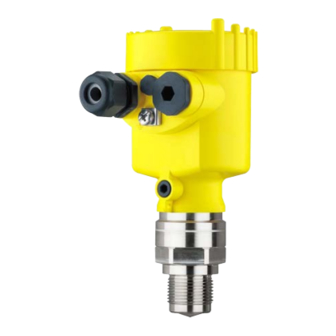
Radar sensor for continuous level measurement of liquids.
4...20 ma/hart - two-wire
Hide thumbs
Also See for VEGAPULS 64:
- Operating instructions manual (100 pages) ,
- Mounting instructions (24 pages) ,
- Quick setup manual (24 pages)
Advertisement
Table of Contents
- 1 Authorised Personnel
- 2 CE Conformity
- 3 Configuration
- 4 Mounting 3.1 Mounting Preparations, Mounting Strap
- 5 Connecting to Power Supply 4.1 Connecting
- 6 Wiring Plan, Single Chamber Housing
- 7 Set up with the Display and Adjustment Module 5.1 Insert Display and Adjustment Module
- 8 Parameter Adjustment - Quick Setup
- 9 Parameter Adjustment - Extended Adjustment
- 10 Supplement 6.1 Technical Data
- 11 Information
- Download this manual
Advertisement
Table of Contents

Related Manuals for Vega VEGAPULS 64


Summary of Contents for Vega VEGAPULS 64
- Page 1 Quick setup guide Radar sensor for continuous level measurement of liquids VEGAPULS 64 4 … 20 mA/HART - two-wire Document ID: 51462...
- Page 2 You can find supplementary information in the corresponding, more detailed Operating Instructions Manual as well as the Safety Manual that comes with instruments with SIL qualification. These manuals are available on the supplied DVD or in the download area of "www.vega. com". Operating instructions VEGAPULS 64 - 4 … 20 mA/HART - two- wire: Document-ID 51141 Editing status of the quick setup guide: 2015-12-04 VEGAPULS 64 •...
-
Page 3: Authorised Personnel
During work on and with the device the required personal protective equipment must always be worn. Appropriate use VEGAPULS 64 is a sensor for continuous level measurement. You can find detailed information about the area of application in chapter "Product description". Operational reliability is ensured only if the instrument is properly used according to the specifications in the operating instructions manual as well as possible supplementary instructions. -
Page 4: Ce Conformity
Protection of the environment is one of our most important duties. That is why we have introduced an environment management system with the goal of continuously improving company environmental pro- tection. The environment management system is certified according to DIN EN ISO 14001. VEGAPULS 64 • 4 … 20 mA/HART - two-wire... - Page 5 1 For your safety Please help us fulfill this obligation by observing the environmental instructions in this manual: • Chapter "Packaging, transport and storage" • Chapter "Disposal" VEGAPULS 64 • 4 … 20 mA/HART - two-wire...
-
Page 6: Configuration
Alternatively, you can access the data via your smartphone: • Download the smartphone app "VEGA Tools" from the "Apple App Store" or the "Google Play Store" • Scan the Data Matrix code on the type label of the instrument or •... -
Page 7: Mounting 3.1 Mounting Preparations, Mounting Strap
– Angle of inclination in two steps 0° and 90° Mounting instructions Polarisation Radar sensors for level measurement emit electromagnetic waves. The polarization is the direction of the electrical component of these waves. The polarization direction is marked by a nose on the housing, see following drawing: Fig. 3: Position of the polarisation Nose for marking the direction of polarisation VEGAPULS 64 • 4 … 20 mA/HART - two-wire... - Page 8 Fig. 5: Mounting of the radar sensor on vessels with conical bottom VEGAPULS 64 • 4 … 20 mA/HART - two-wire...
-
Page 9: Connecting To Power Supply 4.1 Connecting
1 cm (0.4 in) of insulation from the ends of the individual wires 5. Insert the cable into the sensor through the cable entry Fig. 6: Connection steps 5 and 6 - Single chamber housing VEGAPULS 64 • 4 … 20 mA/HART - two-wire... -
Page 10: Wiring Plan, Single Chamber Housing
10. Reinsert the display and adjustment module, if one was installed 11. Screw the housing lid back on The electrical connection is finished. Wiring plan, single chamber housing The following illustration applies to the non-Ex as well as to the Ex-ia version. VEGAPULS 64 • 4 … 20 mA/HART - two-wire... - Page 11 Fig. 8: Electronics and terminal compartment, single chamber housing Voltage supply, signal output For display and adjustment module or interface adapter For external display and adjustment unit Ground terminal for connection of the cable screen VEGAPULS 64 • 4 … 20 mA/HART - two-wire...
-
Page 12: Set Up With The Display And Adjustment Module 5.1 Insert Display And Adjustment Module
The display and adjustment module is powered by the sensor, an ad- ditional connection is not necessary. Fig. 9: Installing the display and adjustment module in the electronics compart- ment of the single chamber housing VEGAPULS 64 • 4 … 20 mA/HART - two-wire... -
Page 13: Parameter Adjustment - Quick Setup
Select the individual menu items with the [->] key. Carry out the steps in the below sequence. 1. Measurement loop name In the first menu item you assign a suitable measurement loop name. Permitted are names with max. 19 characters. 2. Medium In this menu item you select the medium. The selection comprises liquids with different properties. VEGAPULS 64 • 4 … 20 mA/HART - two-wire... - Page 14 In this menu item you carry out the min. adjustment. Enter the measuring distance for 0 % filling. 8. Termination "Quick setup terminated successfully" is displayed briefly. Information: The echo curve of setup was stored automatically during the quick setup. The quick setup is finished. VEGAPULS 64 • 4 … 20 mA/HART - two-wire...
-
Page 15: Parameter Adjustment - Extended Adjustment
To perform the adjustment, enter the distance with full and empty ves- sel, see the following example: VEGAPULS 64 • 4 … 20 mA/HART - two-wire... - Page 16 With the adjustment software PACTware and the PC, the stored echo curves can be displayed with high resolution and used to recognize signal changes over time. In addition, the echo curve saved during setup can also be displayed in the echo curve window and compared with the current echo curve. VEGAPULS 64 • 4 … 20 mA/HART - two-wire...
- Page 17 Displayed value 1 Filling height in % Displayed value 2 Electronics temperature in °C Backlight Switched on Menu - Diagnosis Menu item Parameter Default setting Sensor status Distance Peak value Meas. certainty VEGAPULS 64 • 4 … 20 mA/HART - two-wire...
- Page 18 Linear HART mode Address 0 Special pa- rameters Menu - Info Menu item Parameter Device name VEGAPULS 6. Hardware and software version Instrument version Factory calibration Date date Sensor characteristics Order-specific characteristics VEGAPULS 64 • 4 … 20 mA/HART - two-wire...
- Page 19 The level would then no longer be detectable in this area. If a false signal suppression has already been saved in the sensor, the following menu window appears when selecting "False signal suppression": VEGAPULS 64 • 4 … 20 mA/HART - two-wire...
- Page 20 "Extend", the distance to the product surface of the created false signal suppression is displayed. This value can now be changed and the false signal suppression can be extended to this range. VEGAPULS 64 • 4 … 20 mA/HART - two-wire...
-
Page 21: Supplement 6.1 Technical Data
Permissible residual ripple - Ex-d-ia instrument Ʋ for 18 V< U < 35 V ≤ 1 V (16 … 400 Hz) Load resistor Ʋ Calculation )/0.022 A Ʋ Example - Non-Ex instrument with (24 V - 12 V)/0.022 A = 545 Ω = 24 V DC VEGAPULS 64 • 4 … 20 mA/HART - two-wire... - Page 22 Notes VEGAPULS 64 • 4 … 20 mA/HART - two-wire...
- Page 23 Notes VEGAPULS 64 • 4 … 20 mA/HART - two-wire...
-
Page 24: Information
All statements concerning scope of delivery, application, practical use and operat- ing conditions of the sensors and processing systems correspond to the information available at the time of printing. Subject to change without prior notice © VEGA Grieshaber KG, Schiltach/Germany 2016...
Need help?
Do you have a question about the VEGAPULS 64 and is the answer not in the manual?
Questions and answers