Table of Contents
Advertisement
Quick Links
AtriCure cryoICE BOX, model ACM2 – 230 (220-240)VAC, 2A, 50/60 Hz
AtriCure Europe B.V.
De entree 260
1101 EE Amsterdam
NL
+31 20 7005560
ear@atricure.com
MD
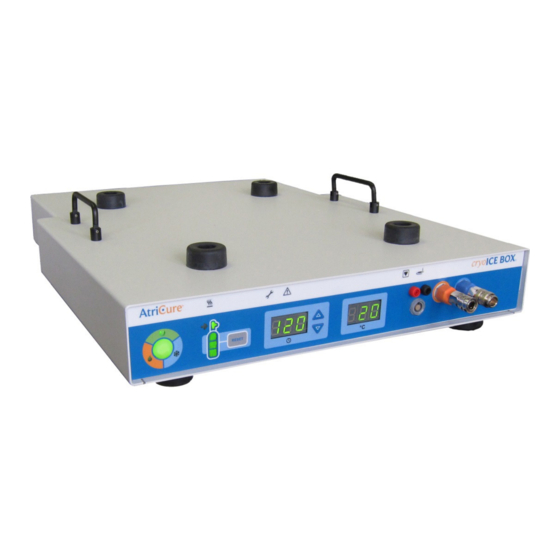
cryoICE BOX
Version 6
INSTRUCTION FOR USE
AtriCure Inc.
7555 Innovation Way
Mason, Ohio 45040 USA
+1 866 349 2342
+1 513 755 4100
2023-04 | IFU-0093.A | en
Advertisement
Table of Contents

Related Manuals for AtriCure cryoICE BOX


Summary of Contents for AtriCure cryoICE BOX
- Page 1 BOX Version 6 INSTRUCTION FOR USE AtriCure cryoICE BOX, model ACM2 – 230 (220-240)VAC, 2A, 50/60 Hz AtriCure Europe B.V. AtriCure Inc. De entree 260 7555 Innovation Way 1101 EE Amsterdam Mason, Ohio 45040 USA +1 866 349 2342...
-
Page 2: Table Of Contents
Meanings of Symbols on AtriCure cryoICE system ........ - Page 3 Disconnecting the AtriCure cryoICE Probe ........
-
Page 4: Foreword
AtriCure’s cryo-ablation probes. The intended purpose of the ACM Exhaust Hose Connector is an optional accessory of the AtriCure cryoICE BOX, providing a method to connect the AtriCure cryoICE BOX exhaust to a hospital medical vacuum or waste anesthesia gas disposal (WAGD) system. -
Page 5: Cautions
Portable RF communications equipment (including peripherals such as antenna cables and external • antennas) should be used no closer than 30 cm (12 inches) to any part of the cryoICE BOX, including cables specified by the AtriCure. Otherwise, degradation of the performance of this equipment could result. - Page 6 Meanings of Symbols on AtriCure Cryo Module Power OFF Cylinder Valve ON/OFF Caution O Gas Gauge Reset Alternating Current Gas Exhaust Equipotential Terminal Maintenance Needed Type CF Applied Part Cylinder Heater Band (PROBE) READY Footswitch FREEZE Maximum Pressure DEFROST Gas Inlet...
-
Page 7: Classification In Accordance With Iec, En, Ansi/Aami, Csa 60601-1
IN ACCORDANCE WITH ANSI/AAMI ES60601-1 (2005) + AMD 1 (2012) CAN/CSA C22.2 No. 60601-1 (2014) E509985 Cryogenic Ablation Device, Model AtriCure Cryo Module, ACM2, cord connected/ appliance coupler / transportable, rated: 230VAC, 2A, 50/60 Hz 1. Type of protection against electric shock: Class I 2. -
Page 8: System Overview
1 . SYSTEM OVERVIEW System Description The ACM is designed to operate only with AtriCure designed and developed AtriCure cryoICE system probes. The cryoICE system probe, cryoICE cryoFORM® probe & cryoSPHERE® probe shall be referred as the AtriCure PROBE in this Instruction for Use. - Page 9 MARK, STRAIGHT 3 .0 M, S000626 10A, 250V POWER CORD - SWITZERLAND, STRAIGHT S000627 3 .0 M, 10A, 250V Table 2: AtriCure Cryo Module Accessories Accessory Part Description Part Number A001150-13 AGSS Type 1L Coupler to .250-18 NPT A001150-14 AGSS Alternate Coupler Assembly...
-
Page 10: The Atricure Cryoice System
• In addition of the Activation Button on the front panel of the ACM, an accessory Footswitch can also be used to activate and terminate the cryo ablation cycle. • The ACM is designed to operate only with AtriCure’s PROBES. Refer to the AtriCure’s PROBE Instruction for Use for detailed use and description. -
Page 11: Operating Modes
Activation Switch or the Footswitch while in the FREEZE Mode. In this mode, the AtriCure’s PROBE temperature is actively forced towards the ambient temperature. Once the AtriCure’s PROBE temperature is above approximately 10°C (50°F), the ACM will transition back to the READY Mode. -
Page 12: Electrical Specifications
AtriCure Cryo Module, model ACM2 – 230 (220-240)VAC, 2A, 50/60 Hz Replace fuses as marked: 2.0A/250V, T-lag, 5 × 20 mm, UL Recognized, IEC Approved AtriCure cryoICE System Probe Temperature Display Accuracy (see figure 2 item 7) Resolution: 1°C (increments) Temperature >... - Page 13 5: N O Inlet Connection Figure Next, match the opposite tank hose connection end of the N O gas line with the threaded connection port of • a new N O gas cylinder. Screw the ACM gas line into place by hand tightening the knob as shown in Figure 6. •...
-
Page 14: Exhaust Tubing
(Turn-ON) or disconnect mains power (Turn-OFF) to the ACM. • After powering ON, the Activation Button on the front of the ACM interface will illuminate. If the button does not illuminate, check for proper power cord connection and switch position. Figure 11: Turn-ON AtriCure Cryo Module with Switch... -
Page 15: Resetting The N O Gas Gauge
Resetting the N O Gas Gauge • Only reset the gauge when a new full cylinder has been installed. Ensure is powered ON. • • Ensure the ACM is in READY mode. • Find the gas cylinder display on the front of the and note the RESET button to the right of this display, see Figure 12. -
Page 16: Device Use
DEVICE Install AtriCure cryoICE System Probe Ensure ACM is properly connected to a N2O gas cylinder. The PROBE may be connected before the ACM has been turned on, while the ACM is being turned on, or when the ACM is on and in READY Mode. -
Page 17: Set Ablation Time
A test run is advised to ensure the PROBE and ACM is working properly prior to the case. Pneumatic connectors should only be unplugged when the ACM is in the READY mode. Set Ablation Time The time of ablation is displayed in the middle of the interface of the ACM and is indicated by a clock under- neath the display. -
Page 18: Set Default Ablation Time
This should only be done at the discretion of a physician as there will not be temperature feed- back. 6 . SYSTEM DISASSEMBLY AFTER USE Check to see that the service icon is not illuminated. If so, contact your local AtriCure representative to correct the problem. Disconnecting the AtriCure... -
Page 19: Preventive Maintenance Program
Visual Inspection (for damages, cracked parts, missing items, leaks, etc.) • • Electrical Safety Check in accordance with IEC 62353 standard For more detailed information about Preventative Maintenance programs, please contact your local AtriCure Service representative. Technical Support Telephone: +31 20 700 55 60 Email: technical.service@atricure.com... -
Page 20: Tank Hose Assembly Without Canisters - Standard
Accessories are expected to remain suitable for its intended purpose, assuming the responsible organization will follow AtriCure’s Instruction For Use for preventative maintenance. AtriCure has defined the Expected Life Time of the ACM to be 5 years. For information on preventative maintenance, please see Preventative Maintenance Program, or contact... -
Page 21: Troubleshooting
8 . TROUBLESHOOTING Note: If the problem persists and could not be resolved by taking the recommended actions in the tables below, please contact your local AtriCure representative. Problem Possible Cause Action Front displays • No power. • Check power switch on back of ACM. - Page 22 Problem Possible Cause Action PROBE not get- • Heater Band not properly installed. • Check heater installation and heater icon. ting cold enough. • N O cylinder low or out of gas. • Replace N O cylinder. • Exhaust filter is clogged. •...
-
Page 23: Atricure Cryoice System Error Codes
If an error condition should occur, the Maintenance Needed Indicator or the System Fault Indicator will illuminate. The PROBE Temperature display on the front panel will temporarily display one of the following error codes during the power-up sequence. Contact your local AtriCure representative if one of these conditions occurs. Error... -
Page 24: Electromagnetic Compatability Tables
Professional healthcare facility environment. b) This test is not applicable in this environment unless the AtriCure cryoICE BOX used there will be connected to the PUBLIC MAINS NETWORK and the power input Is otherwise within the scope of the Basic EMC standard. -
Page 25: Electromagnetic Immunity - Input A.c. Power Port
Guidance and manufacturer’s declaration – Input A.C Power Port Immunity The AtriCure cryoICE BOX is intended for use in the electromagnetic environment specified below. The customer or the user of the AtriCure cryoICE BOX unit should assure that it is used in such an environment. Immunity Test Levels... - Page 26 The test may be performed at any one power input voltage within the AtriCure cryoICE BOX’s RATED voltage range. If the AtriCure cryoICE BOX tested at one power input voltage, It Is not necessary to re-test al additional voltages. b) All AtriCure cryoICE BOX cables are attached during the test.
-
Page 27: Electromagnetic Immunity - Input D.c. Power Port - Not Applicable
Guidance and manufacturer’s declaration – Patient Coupling Port Immunity The AtriCure cryoICE BOX is intended for use in the electromagnetic environment specified below. The customer or the user of the AtriCure cryoICE BOX unit should assure that it is used in such an environment. -
Page 28: Warranties
(1) adversely affected due to use with devices manufactured or distributed by parties not authorized by AtriCure, Inc. (2) repaired or altered outside AtriCure’s factory in a way so as to, in AtriCure’s judgment, affect its stability or reliability, (3) subjected to im- proper use, negligence or accident, or (4) used other than in accordance with the design and use parameters, instructions and guidelines for the product or with functional, operational or environmental standards for similar products generally accepted in the industry.
Need help?
Do you have a question about the cryoICE BOX and is the answer not in the manual?
Questions and answers