
Related Manuals for AtriCure ASU3-230


Summary of Contents for AtriCure ASU3-230
- Page 1 ABLATION AND SENSING UNIT (ASU) USER’S MANUAL Model ASU2-115 Model ASU3-230 AtriCure Incorporated 7555 Innovation Way Mason, Ohio 45040 USA Customer Service: 1-866-349-2342 (toll free) 1-513-755-4100 (phone) P000463 Rev. F...
- Page 3 USER’S MANUAL European Representative: Herbert Köntges Köntges SPRL Avenue Hellevelt 35 B-1180 Brussels Belgium Tel: +32 2 375 51 63 FAX: +32 2 375 89 06 email: herbert.kontges@skynet.be...
-
Page 4: Table Of Contents
Warnings and Precautions ....................4 EMC Guidance and Manufacturer’s Declaration ............... 7 1.4. 1.5. Responsibility of the Manufacturer .................. 10 THE ATRICURE ABLATION AND SENSING UNIT (ASU) ..........11 2.1. Device Description ......................11 ASU Front Panel – Illustration and Nomenclature ............11 2.2. - Page 5 USER’S MANUAL 8.2. Cleaning and Disinfecting ....................34 DISPOSAL ............................ 35 10. ACCESSORIES ..........................35 10.1. ASB1, Source Switch Accessory ..................35 10.2. ASB3, Switch Matrix Accessory ..................37 11. ADDITIONAL ACCESSORIES AND CABLES ..............39 Page 2 of 39 P000463.F...
-
Page 6: Getting Started
Bipolar Handpiece uses power above 30 Watts. The operating mode is a function of the handpieces or pen and is set by the ASU. The AtriCure ASU is designed to operate only with an AtriCure Bipolar Handpiece, AtriCure Isolator Pen, or AtriCure CoolRail linear pen. -
Page 7: System Description
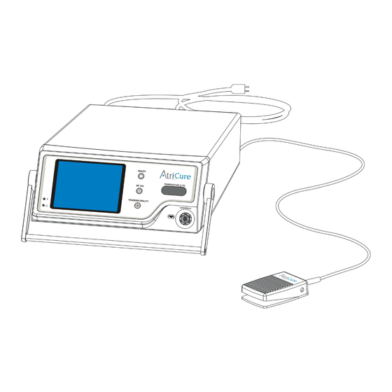
USER’S MANUAL 1.1. System Description As shown in Figure 1, the system is comprised of the following: • AtriCure Bipolar Handpiece with integral cable (not shown) • AtriCure Ablation and Sensing Unit (ASU) • Footswitch • Power cord. Accessory devices are described in paragraph 10. - Page 8 • The use of accessories, transducers and cables other than those specified in accordance with the instructions or supplied by AtriCure, may result in increased emissions or decreased immunity of the equipment. • The ASU should not be used adjacent or stacked with other equipment, except for intended stacking with AtriCure’s equipment in accordance with the instructions.
- Page 9 Handpiece. 1.3.2. PRECAUTIONS • Use only with the AtriCure Handpieces intended for use with the ASU. • Do not activate the ASU until the Handpiece is properly positioned in the patient.
-
Page 10: Emc Guidance And Manufacturer's Declaration
Guidance and manufacturer’s declaration – electromagnetic emissions The AtriCure Ablation and Sensing Unit (ASU) is intended for use in the electromagnetic environment specified below. The customer or the user of the ASU unit should assure that it is used in such an environment. - Page 11 Guidance and manufacturer’s declaration – electromagnetic immunity The AtriCure Ablation and Sensing Unit (ASU) is intended for use in the electromagnetic environment specified below. The customer or the user of the ASU unit should assure that it is used in such an environment.
- Page 12 Guidance and manufacturer’s declaration – electromagnetic immunity The AtriCure Ablation and Sensing Unit (ASU) is intended for use in the electromagnetic environment specified below. The customer or the user of the ASU should assure that it is used in such an environment.
-
Page 13: Responsibility Of The Manufacturer
AtriCure Ablation and Sensing Unit The AtriCure Ablation and Sensing Unit (ASU) is intended for use in an electromagnetic environment in which radiated RF disturbances are controlled. The customer or the user of the ASU can help prevent electromagnetic... -
Page 14: The Atricure Ablation And Sensing Unit (Asu)
Handpiece uses power above 30 Watts. The operating mode is a function of the handpiece and is set by the ASU. The AtriCure ASU is designed to operate with the AtriCure Handpiece. The ASU and Handpiece are designed for use without a neutral electrode. The Footswitch is the input device used to activate RF energy delivery. - Page 15 USER’S MANUAL Front Panel Displays There are two displays on the front panel of the ASU: the Tissue Conductance / Power Graph Display and the Temperature Display. These two displays are described below. Display Description Tissue Conductance Graph Display – Isolator clamp (Default): During the ablation cycle the ASU displays a graph of tissue conductance (Current/Voltage)
- Page 16 Front Panel Receptacle Receptacle Description HANDPIECE or ASU Accessory Receptacle This 12-pin receptacle accepts the AtriCure Handpiece or connection cable to an accessory device. This connection is patient-isolated. Page 13 of 39 P000463.F...
-
Page 17: Asu Rear Panel - Illustration And Nomenclature
USER’S MANUAL 2.3. ASU Rear Panel – Illustration and Nomenclature An illustration of the ASU rear panel is shown in Figure 3, below. Figure 3 – ASU Rear Panel 1. Data Port 5. Equipotential Ground Stud 2. Speaker Volume Control 6. - Page 18 Graphic Description Equipotential Ground Stud – Provides a means of securely linking the earth grounds of the AtriCure ASU to other grounded equipment. Data Port – For manufacturing and test purposes. Power Entry Module – This module contains both the ON/OFF switch and the fuses. The voltage is selected by the orientation of the fuse drawer as marked.
-
Page 19: Installing The Asu
3. Installing the ASU Inspect the ASU for any signs of physical damage to the front panel, chassis or cover. NOTE: If any physical damage is found, DO NOT USE THE UNIT. CONTACT AtriCure for a replacement. All returns must be approved by AtriCure. -
Page 20: Connecting And Disconnecting The Handpiece
Inspect the Footswitch for any signs of physical damage to the cable and connector. If physical damage is found or the Footswitch does not perform within specification, notify AtriCure. All returns must have approval from AtriCure. 3.6.2. Connecting and Disconnecting the Footswitch With the connector alignment arrow in the 12 o’clock position, push the Footswitch... - Page 21 USER’S MANUAL Figure 4 – Connecting the Footswitch to the ASU 3.6.3. Preparing the Footswitch for Use The Footswitch should be placed on a flat floor. It is recommended that the area near the Footswitch be kept dry to reduce the risk of slippage. Appropriate precautions should be taken to ensure that the cable connecting the Footswitch to the ASU does not create a hazard in the operating room.
-
Page 22: Instructions For Use
4. Instructions For Use 4.1. Powering Up the ASU 1. Ensure that the ASU has been plugged into a grounded receptacle. NOTE: Do not use extension cords or three-prong to two-prong adapters. The power cord assembly should be periodically checked for damaged insulation or connectors. 2. -
Page 23: Operating Modes
USER’S MANUAL 4.2. Operating Modes The ASU operates in one of five modes: STANDBY, READY, RF ON, ERROR and FAULT modes. These modes are shown on the lower left corner of the Conductance Display Graph. See Figure 6, below. • STANDBY Mode – This mode is entered automatically after the ASU is successfully turned on or from READY Mode upon detection of a Handpiece or Footswitch disconnection. -
Page 24: Audio Tones
4.3. Audio Tones The ASU uses 7 possible audio tones during its operation: Start Tone, Error Tone, Fault Tone, RF ON Tone, Transmurality Tone, High Temperature RF ON Tone, and the High Temperature Transmurality Tone. You may control the volume of these tones using the Speaker Volume Control on the rear panel of the ASU (See Figure 3). -
Page 25: Delivering Rf Energy
USER’S MANUAL 4.4. Delivering RF Energy 4.4.1. Connect the Handpiece and Footswitch Connect the Handpiece and Footswitch as described in Sections 3.5. and 3.6., and note the display to ensure connections are made. The display screen and Ready Indicator of the ASU should indicate that the RF generator is in the READY mode. - Page 26 4.4.2. Position the Handpiece To position the Handpiece, follow the Instructions for Use provided with the Handpiece. 4.4.3. Deliver RF Energy Press the Footswitch to initiate RF energy output. RF energy output is terminated by releasing the Footswitch or at the end of 40 continuous seconds of energy delivery. The display screen of the ASU will indicate that the generator is in the RF ON mode.
- Page 27 USER’S MANUAL Figure 9 – Power Display Graph Indicating RF ON Mode Both the conductance and the power graphs are on a 20-second scale. In some cases, the transmurality condition will not be achieved within the 20 seconds shown on the Tissue Conductance Display Graph (not valid for Isolator...
-
Page 28: Troubleshooting
Internal ASU failure Contact AtriCure Customer Service If the lack of ASU RF power output persists, contact the AtriCure service representative. 5.2. Error Codes If a fault condition should occur, the numeric displays on the front panel will display an error code. -
Page 29: Electromagnetic Or Other Interference
• Connect the ASU into an outlet on a circuit different from that to which the other device(s) are connected. • Contact the AtriCure service representative for help. Use the following sections to troubleshoot specific types of interference, including monitor (display) interference, neuromuscular stimulation, and pacemaker interference. - Page 30 5.3.1.2. Interference Only When ASU is Activated 1. Check all connections to the ASU, and active accessory to look for possible metal-to-metal sparking. 2. If interference continues when the ASU is activated and while the electrode is not in contact with the patient, the monitor is responding to radio frequencies. Some manufacturers offer RF choke filters for use in the monitor leads.
-
Page 31: Symbols Used
USER’S MANUAL 6. Symbols Used Alternating Current Attention: consult accompanying documents Dangerous Voltage Type CF Defibrillation-Proof Applied Part Type CF Applied Part READY RF ON Transmurality Equipotential Footswitch Fuses Non-Ionizing Radiation Power OFF Power ON Speaker Page 28 of 39 P000463.F... -
Page 32: Technical Specifications
7. Technical specifications 7.1. RF Output • Frequency: 460 kHz 5%, Quasi-sinusoidal • ASU Maximum Power Output: 32.5 W at 100 • HF Power and Voltage Output: Device Maximum Maximum Handpiece Type Code Output Power Output Voltage 57.0 Vrms 28.5 W at 114 Isolator... -
Page 33: Electrical Specifications
The ASU is capable of producing a maximum output power of 32.5 Watts under a 100 Ohm load although no current AtriCure Bipolar Handpiece uses power above 30 Watts. The maximum output voltage depends on the device code, and can be either 57 Vrms or 77.5 Vrms. - Page 34 Figure 11 – Power vs. Load (clamp algorithm) Page 31 of 39 P000463.F...
- Page 35 USER’S MANUAL ASU2 & ASU3 POWER OUTPUT Device Code L Device Code K Device Code J Device Code B Device Code C 1000 1100 1200 Load Impedance (Ohms) Figure 12 – Power vs. Load (pen algorithm) Page 32 of 39 P000463.F...
-
Page 36: Preventive Maintenance And Cleaning Of Asu
Visually inspect the footswitch for fluids or other infectious hazards. Clean as necessary using the instructions in Section 8.2. The ASU does not have any serviceable parts. For servicing issues, contact AtriCure, Inc. at: AtriCure Incorporated 7555 Innovation Way... -
Page 37: Cleaning And Disinfecting
7. If soil remains on the white cloth, repeat steps 3 through 6. 8. After cleaning is complete, turn the unit on to perform Power On Self-Test (POST). If any errors are received, contact AtriCure to begin return process. Page 34 of 39... -
Page 38: Disposal
• OSCOR Model PACE 203H ™ WARNING: Read auxiliary device manual and observe warnings. Any AtriCure handpiece or pen device may be connected to the Source Switch when the Source Switch is in the ASU position. The Auxiliary input switch position (AUX) is to be used only with AtriCure Isolator... - Page 39 USER’S MANUAL Source Switch set up is shown in the following figures. Figure 13 Figure 14 Page 36 of 39 P000463.F...
-
Page 40: Asb3, Switch Matrix Accessory
▪ MicroPace ORLab™ Stimulator/EP Recorder System WARNING: Read auxiliary device manual and observe warnings. Any AtriCure handpiece or pen device may be connected to the Switch Matrix. AtriCure Devices will be functional when the device is connected to the correct receptacle and the Switch Matrix switch knob is turned to indicate the device for use. - Page 41 USER’S MANUAL ASB3, Switch Matrix Unit is shown below with the ASU. Page 38 of 39 P000463.F...
-
Page 42: Additional Accessories And Cables
Switch Matrix set up is shown in the following figures. 11. Additional Accessories and Cables • ASU/ASB Power Cord • ASU/ASB Interface Cable • Auxiliary Cable • ASU Footswitch • ASU/ASB Footswitch Interface Cable Page 39 of 39 P000463.F... - Page 43 AtriCure’s obligation under this warranty is limited to the repair or replacement, at its option, of any product, or part thereof, which has been returned to AtriCure, Inc. or its Distributor within the applicable time period shown below and which examination disclosed, to AtriCure’s satisfaction, to be defective.
Need help?
Do you have a question about the ASU3-230 and is the answer not in the manual?
Questions and answers