Table of Contents
Advertisement
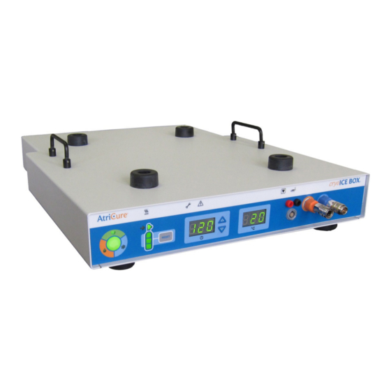
AtriCure cryoICE BOX, model ACM1 – 115 (100-120)VAC, 4A, 50/60 Hz
AtriCure cryoICE BOX, model ACM2 – 230 (220-240)VAC, 2A, 50/60 Hz
European Representative:
Herbert Köntges
Köntges SPRL
Avenue Hellevelt 35
B-1180 Brussels Belgium
Tel: +32 (0) 2 375 51 63
FAX: +32 (0) 2 375 89 06
email:
herbert.kontges@skynet.be
cryoICE BOX
Version 6
USER'S MANUAL
i
Manufactured by: AtriCure, Inc.
7555 Innovation Way,
Mason, Ohio 45040 USA
1.866.349.2342
P001323 Rev A
Advertisement
Table of Contents

Related Manuals for AtriCure cryoICE BOX ACM1


Summary of Contents for AtriCure cryoICE BOX ACM1
- Page 1 BOX Version 6 USER’S MANUAL AtriCure cryoICE BOX, model ACM1 – 115 (100-120)VAC, 4A, 50/60 Hz AtriCure cryoICE BOX, model ACM2 – 230 (220-240)VAC, 2A, 50/60 Hz European Representative: Herbert Köntges Köntges SPRL Avenue Hellevelt 35 B-1180 Brussels Belgium Tel: +32 (0) 2 375 51 63 Manufactured by: AtriCure, Inc.
-
Page 2: Table Of Contents
CAUTIONS .......................... vi SAFETY CSA MARK INFORMATION ................ix SYSTEM OVERVIEW ....................... 1 The AtriCure cryoICE BOX ....................1 AtriCure cryoICE BOX Front and Rear Panels – Illustrations and Nomenclature ....1 Operating Modes ........................3 READY Mode ........................3 FREEZE Mode........................3 DEFROST Mode ........................ - Page 3 Operate Without Temperature Reading ................14 SYSTEM DISASSEMBLY AFTER USE ................15 Disconnecting the AtriCure cryoICE Probe .................15 O Cylinder Removal ......................15 PREVENTIVE MAINTENANCE AND CLEANING OF THE ATRICURE CRYOICE BOX ............................. 16 Cleaning and Disinfecting Instructions .................16 Preventive Maintenance ......................17 AtriCure Address / Toll Free Telephone Number ..............18...
-
Page 4: Foreword
This manual and the equipment it describes are for use only by qualified medical professionals trained in the particular technique and surgical procedure to be performed. The AtriCure cryoICE BOX also referred to as the AtriCure Cryo Module (ACM) consisting of two model units: ACM1 and ACM2. -
Page 5: Patent Information
The safe and effective use of the cryo device and equipment is highly dependent upon factors under the control of the operator. There is no substitute for a properly trained operating room staff. It is important that the operating instructions supplied with the AtriCure cryoICE BOX unit be read, understood, and followed before use. -
Page 6: Cautions
BOX, including cables specified by the AtriCure. Otherwise, degradation of the performance of this equipment could result. • Note: The Emissions characteristics of this equipment make it suitable for use in industrial areas and hospitals (CISPR 11 class A). If it is used in a residential environment (for which CISPR 11 class B is normally required) this equipment might not offer adequate protection to radio-frequency communication services. - Page 7 Meanings of Symbols on AtriCure cryoICE BOX Power Off Caution Alternating Current Equipotential Terminal Type CF Applied Part (cryoICE Probe) READY FREEZE DEFROST O Gas Gauge Timer Timer Increase Button Timer Decrease Button cryoICE Probe Temperature Thermocouple/Probe Cylinder Valve On/Off...
- Page 8 Maintenance Needed Fault Condition Cylinder Heater Band Footswitch Maximum Pressure Gas Inlet Gas Outlet Non-Sterile Manufacturer Catalog Number Serial Number Prescription Only Follow Instructions for Use Humidity and Temperature Storage Limits Waste Electrical and Electronic Equipment (WEEE) viii...
-
Page 9: Safety Csa Mark Information
CLASS 8750 81 - MEDICAL ELECTRICAL EQUIPMENT/SYSTEMS - Certified to US Standards Cryogenic Ablation Device, Model AtriCure Cryo Module, ACM1 & ACM2, cord connected/ appliance coupler / transportable, rated: 115/230Vac, 4/2A, 50/60 Hz 1. Type of protection against electric shock: Class I 2. -
Page 10: System Overview
Footswitch can also be used to activate and terminate the cryo ablation cycle. • The cryoICE BOX is designed to operate only with AtriCure cryoICE probes. Refer to the cryoICE probe Instruction for Use for complete description and indications for use of these devices. - Page 11 Figure 2: AtriCure cryoICE BOX Rear Panel (Domestic & International) 17. N O Exhaust Port 23. Power Plug Receptacle 18. N O Manual Exhaust Knob 24. Power Switch 19. N O Inlet Port 25. Mains Fuse Location 20. N O Exhaust Switch 26.
-
Page 12: Operating Modes
Operating Modes The cryoICE BOX operates in one of three modes: READY, FREEZE, and DEFROST. These modes are identified by the system status indicator LEDs and the ablation status indicator LEDs located on the front of the cryoICE BOX unit. READY Mode This mode is entered automatically upon successful execution of Power-on-self - test when the unit is first turned on or following DEFROST Mode upon the... -
Page 13: Technical Specifications
-20°F to +100°F Electrical Specifications AtriCure cryoICE BOX, model ACM1 – 115 (100-120)VAC, 4A, 50/60 Hz AtriCure cryoICE BOX, model ACM2 – 230 (220-240)VAC, 2A, 50/60 Hz Mains Fuses AtriCure cryoICE BOX, model ACM1 – 115 (100-120)VAC, 4A, 50/60 Hz Replace fuses as marked: 4.0A/250V, T-lag, 5 ×... -
Page 14: Atricure Cryoice Box, Detachables, And Accessories
F: AtriCure cryoICE BOX Footswitch (Optional – not shown) - Accessory G: AtriCure cryoICE BOX Power Cord (not shown) - Detachable H: AtriCure cryoICE probe with integral tube set (not shown) - Type CF Applied Part I: AtriCure cryoICE BOX Heater Band Extension Spring (not shown) – Detachable... -
Page 15: Atricure Cryoice Box Set-Up And Preparation
AtriCure cryoICE BOX Set-Up and Preparation This section will outline the preliminary set-up for the cryoICE BOX, including cylinder installation, heater band installation, turning on the cryoICE BOX, and resetting the cylinder gauge on the cryoICE BOX user interface. Note: The cryoICE BOX should be set up at least 15-minutes prior to the procedure to allow time for the heater to warm the N O cylinder to operating temperature. - Page 16 Figure 5: Attach Black Knob to Threaded Connection Figure 6: Turn Valve Counter-Clockwise to Open • Listen for leaks. If a leak is detected, tighten the black knob with a wrench if needed. • If the Low-Pressure indicator, as seen in Figure 7, illuminate’s amber this indicates that the cryoICE BOX is not detecting proper pressure.
-
Page 17: Exhaust Tubing
Figure 7: Low Pressure Indicator Exhaust Tubing • Note: Ensure the Exhaust tubing (hose) is firmly attached to the cryoICE BOX N exhaust port, see Figure 2 item 17. • Be sure to route the N O vent tubing to a safe area prior to use. •... -
Page 18: Turning On The Atricure Cryoice Box
Figure 8: Secure All Tensioning Spring Retainers Figure 9: Plug Heater Band Cord into Receptacle Turning On the AtriCure cryoICE BOX • Plug in the cryoICE BOX unit into an approved hospital outlet. • Turn-On the cryoICE BOX unit with the switch located on the back as seen in Figure 10. -
Page 19: Resetting The N O Gas Gauge
Figure 10: Turn-On AtriCure cryoICE BOX with Switch Resetting the N O Gas Gauge • Only reset the gauge when a new full cylinder has been installed. • Ensure cryoICE BOX is powered on. • Ensure the unit is in READY mode. -
Page 20: System Check
System Check • Verify neither the Maintenance Needed or System Fault icons are illuminated. 4. DEVICE USE Install AtriCure cryoICE Probe 1. Ensure cryoICE BOX is properly connected to a N O gas cylinder. 2. The cryoICE probe may be connected before the cryoICE BOX has been turned on, while the cryoICE BOX is being turned on, or when the cryoICE BOX unit is on and in READY mode. - Page 21 4. Ensure each pneumatic connection is fully seated by listening for an audible “click” as each connector engages its receptacle. Gently tug on each tube to ensure proper engagement with connector. 5. Insert the corresponding red and black colored connections into the thermocouple connectors, see Figure 15.
-
Page 22: Set Ablation Time
Set Ablation Time 1. The time of ablation is displayed in the middle of the interface of the cryoICE BOX and is indicated by a clock underneath the display. The display shows the time of ablation in seconds, see Figure 17. Figure 17: Ablation Time Display 2. -
Page 23: Special Cases
5. SPECIAL CASES Abort FREEZE To stop ablation during a FREEZE cycle, press and release the Activation Button during the ablation. The system will then transition into DEFROST mode. Change Ablation Time during Ablation To change the current ablation time, the up and down arrows can be used to add or decrease time in 10 second increments. -
Page 24: System Disassembly After Use
6. SYSTEM DISASSEMBLY AFTER USE Check to see that the service icon is not illuminated. If so, notify AtriCure service to correct the problem. Disconnecting the AtriCure cryoICE Probe 1. The cryoICE probe can only be removed in the READY mode. -
Page 25: Preventive Maintenance And Cleaning Of The Atricure Cryoice Box
7. If soil remains on the white cloth, repeat steps 3 through 6. After cleaning is complete, turn the unit on to perform Power On Self-Test (POST). If any errors are received, contact AtriCure to begin return process. -
Page 26: Preventive Maintenance
Preventive Maintenance AtriCure service representatives or the hospital biomed personnel shall conduct annual preventative maintenance procedures to ensure all cryoICE BOX components are functioning as defined within this manual. Pay particular attention to operational and safety features, including but not limited to: •... -
Page 27: Atricure Address / Toll Free Telephone Number
230V (ACM2). The Rating Label below the Power Entry Module on the back panel of the cryoICE BOX indicates the selected Input Voltage for this unit. This setting should only be adjusted by the manufacturer or by an authorized AtriCure technical service representative. - Page 28 Using the needle nose pliers, carefully extract the fuse box from the power entry module by squeezing down on the fuse box tabs in the slots as shown in Figure 18. Figure 18: Fuse Box Tabs Replace the (2) two fuses located in the fuse box. Make sure the fuses are aligned properly.
-
Page 29: Tank Hose Assembly Without Canisters - Standard
Existing AtriCure cryoICE BOX Upgrade A001056 Packaged, Gas Line Hose Module Assembly- Domestic A001055 Packaged, Tank Hose Assembly- International Figure 20: N O Cylinder Interface Figure 21: AtriCure cryoICE BOX Tank Hose Assembly without canisters Replacement Part Component “C” Tip Washer AtriCure F021837... -
Page 30: Tank Hose Assembly With Canisters - Alternate (Replacement Of Desiccant Filter)
This section only applies to cryoICE Box Systems equipped with the Tank Hose Assembly which contains the canister set. Tank Hose Assembly with Canisters Replacement Parts Item Supplied By Part Number Filter Cartridge AtriCure F021720 Filter O-ring AtriCure F010924 Tip Washer AtriCure... -
Page 31: Disposal
9. Remove the old Tip Washer and replace it with the new washer. Other Detachable and Accessory Devices Supplied International Item Part Number Part Number ACM Footswitch AtriCure A000708 A000708 Tank Hose Assembly with canisters AtriCure A000837 A000838 Tank Hose Assembly without canisters... -
Page 32: Troubleshooting
BOX. • Check AC plug in wall socket. • Ensure power is available at wall socket. • cryoICE BOX electrical failure. • Call AtriCure Service. Cylinder Heater • Heater not plugged in. • Check connection on back of Band Icon unit. - Page 33 • Malfunctioning cryoICE probe. • Replace cryoICE probe. • Electromagnetic interference • Relocate or Reorient cryoICE • cryoICE BOX malfunctioning. • Call AtriCure Service. Bottom segment • N O cylinder empty. • Replace with full cylinder. on N O icon •...
- Page 34 (usually clicks) • Quick connector O-ring dried • Lubricate the connector inside out and/or swelling. with silicon-based O-ring. lubrication such as AtriCure Part No. C002502. Wrench Icon • Heater band over temperature • Unplug heater band if clicking flashing and due to empty N O Cylinder.
- Page 35 • The N O quality is not adequate • Medical grade nitrous oxide, to be used as a refrigerant. 3ppm water maximum, is preferred for use with AtriCure cryogenic Devices. • N O cylinder contains a siphon • Verify the N O cylinder does not tube or a dip tube.
-
Page 36: Atricure Cryoice Box Error Codes
If an error condition should occur, the Maintenance Needed Indicator or the System Fault Indicator will illuminate. The probe Temperature display on the front panel will temporarily display one of the following error codes during the power-up sequence. Contact AtriCure Service if one of these conditions occurs. -
Page 37: Electromagnetic Compatability Tables
This test level assumes a minimum distance between the AtriCure cryoICE BOX and sources of power frequency magnetic field of at least 15 cm. If the RISK ANALYSIS shows that the AtriCure cryoICE BOX will be used closer than 15 cm to sources of power frequency magnetic field, the IMMUNITY TEST LEVEL shall be adjusted as appropriate for the minimum expected distance. -
Page 38: Electromagnetic Immunity - Input A.c. Power Port
The test may be performed at any one power input voltage within the AtriCure cryoICE BOX’s RATED voltage range. If the AtriCure cryoICE BOX is tested at one power input voltage, It Is not necessary to re-test al additional voltages. -
Page 39: Electromagnetic Immunity - Input D.c. Power Port - Not Applicable
This can occur due to magnetic flux saturation of the transformer core after the voltage dip. If this occurs, the AtriCure cryoICE BOX shall provide BASIC SAFETY during and after the test. r) For ME EQUIPMENT and ME SYSTEMS that have multiple voltage settings or auto ranging voltage capability, the test shell be performed at the minimum and maximum RATED input voltage. -
Page 40: Warranties
(1) adversely affected due to use with devices manufactured or distributed by parties not authorized by AtriCure, Inc. (2) repaired or altered outside AtriCure’s factory in a way so as to, in AtriCure’s judgment, affect its stability or reliability, (3) subjected to improper use, negligence or accident, or (4) used other than in accordance with the design and use parameters, instructions and guidelines for the product or with functional, operational or environmental standards for similar products generally accepted in the industry.
Need help?
Do you have a question about the cryoICE BOX ACM1 and is the answer not in the manual?
Questions and answers