
Related Manuals for AtriCure cryoICE BOX1


Summary of Contents for AtriCure cryoICE BOX1
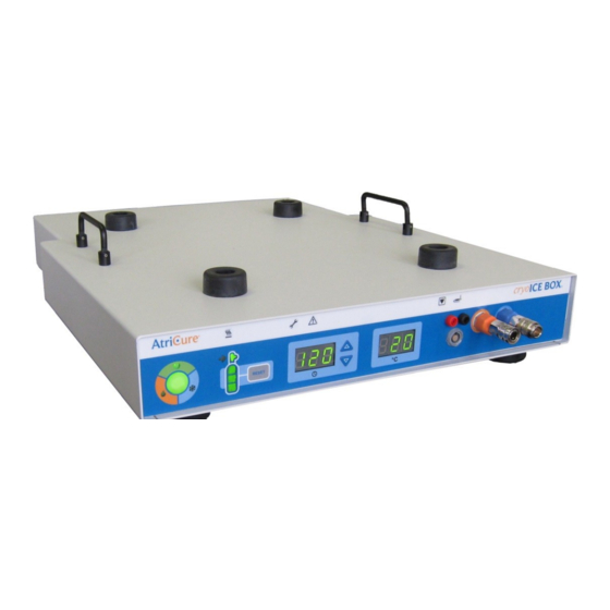
- Page 1 BOX Version 6 USER’S MANUAL Model cryoICE BOX1 – 115 VAC Model cryoICE BOX2 – 230 VAC...
- Page 2 AtriCure, Inc. 7555 Innovation Way Mason, Ohio 45040 P001207 Rev A...
-
Page 3: Table Of Contents
Table of Contents FOREWORD..........................IV PATENT INFORMATION......................IV Warnings and Precautions.......................v WARNINGS..........................v PRECAUTIONS........................v MEANINGS OF SYMBOLS ON CRYOICE BOX..............VI MEANINGS OF SYMBOLS ON CRYOICE PROBE..............VIII SAFETY CSA MARK INFORMATION...................VIII SYSTEM OVERVIEW......................1 cryoICE BOX Front and Rear Panels – Illustrations and Nomenclature........2 Operating Modes..........................3 READY Mode......................3 ... - Page 4 Change Ablation Time during Ablation..................14 Emergency Stop..........................14 Set Default Ablation Time......................14 Operate without temperature reading....................14 SYSTEM DISASSEMBLY AFTER USE................15 Disconnecting the cryoICE Probe....................15 O Cylinder Removal.........................15 PREVENTIVE MAINTENANCE AND CLEANING OF THE CRYOICE BOX....16 Cleaning and Disinfecting Instructions..................16 Preventive Maintenance........................16 Replacement of AC Line Fuses....................17 Tank Hose Accessory –...
-
Page 5: Foreword
The cryoICE BOX is designed to operate only with AtriCure designed and developed cryoICE Probes. For the user’s convenience, the AtriCure Cryo Module will be referred to in this User’s Manual as the “cryoICE BOX”. The AtriCure cryoICE Probe will be referred in this User’s Manual as the “cryoICE Probe”. -
Page 6: Warnings And Precautions
BOX and that no thermocouple wires are exposed from the cable, connector, or the cryoICE PROBE. PRECAUTIONS Use only with the AtriCure cryoICE Probes intended for use with the cryoICE BOX. Do not transition into FREEZE mode until the cryoICE Probe is properly positioned ... -
Page 7: Meanings Of Symbols On Cryoice Box
Meanings of Symbols on cryoICE BOX Attention: consult accompanying documents Dangerous Voltage Power OFF Alternating Current Equipotential Terminal Type CF Applied Part READY FREEZE DEFROST O Gas Gauge Timer Timer Increase Button... - Page 8 Timer Decrease Button cryoICE Probe Temperature Thermocouple/Probe Cylinder Valve On/Off O Gas Gauge Reset Gas Exhaust Maintenance Needed Cylinder Heater Band viii...
-
Page 9: Meanings Of Symbols On Cryoice Probe
Footswitch Maximum Pressure Gas Inlet Gas Outlet Humidity and Temperature Storage Limits (located on corrugated cardboard packaging) Meanings of Symbols on cryoICE Probe Classification in accordance with EN 60601-1 Safety CSA Mark Information... - Page 10 CLASS 8750 81 - MEDICAL ELECTRICAL EQUIPMENT/SYSTEMS - Certified to US Standards Cryogenic Ablation Device, Model AtriCure Cryo Module, ACM1 & ACM2, cord connected/ appliance coupler / transportable, rated: 115/230Vac, 4/2A, 50/60Hz. 1. Type of protection against electric shock: Class I 2.
-
Page 11: System Overview
Footswitch can also be used to activate and terminate the cryo ablation cycle. The cryoICE BOX is designed to operate only with AtriCure cryoICE Probes. Please refer to the cryoICE Probe Instructions for Use P0001031 with CRYO2, P000678 with CRYO3, or P001060 with CRYOFORM. -
Page 12: Cryoice Box Front And Rear Panels - Illustrations And Nomenclature
cryoICE BOX Front and Rear Panels – Illustrations and Nomenclature Illustrations of the cryoICE BOX front panel (Figure 1) and rear panel (Figure 2) are shown below. Figure 1: cryoICE BOX Front Panel Figure 2: cryoICE BOX Rear Panel Activation Button 15. -
Page 13: Operating Modes
Operating Modes The cryoICE BOX operates in one of three modes: READY, FREEZE, and DEFROST. These modes are identified by the system status indicator LEDs and the ablation status indicator LEDs located on the front of the cryoICE BOX unit. READY Mode ... -
Page 14: Technical Specifications
BOX2: 220-240VAC, (230 VAC nominal), 50/60 Hz Mains Fuses cryoICE BOX1 (100 -120VAC, 50 / 60 Hz,): Replace fuses as marked: 4.0A/250V, T-lag, 5 20 mm, UL Recognized, IEC Approved cryoICE BOX2 (220-240VAC, 50 / 60 Hz,): Replace fuses as marked: 2.0A/250V, T-lag, 5 ... -
Page 15: Cryoice Box And Accessories
BOX and Accessories As shown in Figure 3, the system is comprised of the following: A: AtriCure Cryo Module Cylinder Heater Band (CMH15 or CMH22) B: cryoICE BOX N2O Gas Line Hose Module, standard C: cryoICE BOX N O Exhaust Hose... -
Page 16: Cryoice Box Set-Up And Preparation
cryoICE BOX Set-Up and Preparation This section will outline the preliminary set-up for the cryoICE BOX, including cylinder installation, heater band installation, turning on the cryoICE BOX, and resetting the cylinder gauge on the cryoICE BOX user interface. NOTE: The cryoICE BOX should be set up at least 15-minutes prior to the procedure to allow time for the heater to warm the N O cylinder to operating temperature. - Page 17 Figure 5: Attach Black Knob to Threaded Connection Figure 6: Turn Valve Counter-Clockwise to Open Listen for leaks. If a leak is detected, tighten the black knob with a wrench if needed. If the Low-Pressure indicator, as seen in Figure 7, illuminate’s amber this ...
-
Page 18: Exhaust Tubing
Figure 7: Low Pressure Indicator Exhaust tubing NOTE: Ensure the Exhaust tubing (hose) is firmly attached to the cryoICE BOX N2O exhaust port, see Figure 2 item 17. Be sure to route the N O vent tubing to a safe area prior to use. ... -
Page 19: Turning On The Cryoice Box
Figure 8: Secure All Tensioning Spring Retainers Figure 9: Plug Heater Band Cord into Receptacle Turning On the cryoICE BOX Plug in the cryoICE BOX unit into an approved hospital outlet. Turn on the cryoICE BOX unit with the switch located on the back as seen in ... -
Page 20: Resetting The N 2 O Gas Gauge
Figure 10: Turn on cryoICE BOX with Switch Resetting the N O Gas Gauge Only reset the gauge when a new full cylinder has been installed Ensure cryoICE BOX is powered on Ensure the unit is in “READY” mode ... -
Page 21: Meaning Of Gas Gauge Indicators Seen In Figure 12
Meaning of gas gauge indicators seen in Figure 12 Figure 12: N O Gauge Indicators 3-segments on = approximately 40 minutes remaining 2-Segments on = approximately 30 minutes remaining 1-segment on = approximately 20 minutes remaining ... - Page 22 Ensure each pneumatic connection is fully seated by listening for an audible “click” as each connector engages its receptacle. Gently tug on each tube to ensure proper engagement with connector. Insert the corresponding red and black colored connections into the thermocouple connectors, see Figure 15.
-
Page 23: Set Ablation Time
Set Ablation Time The time of ablation is displayed in the middle of the interface of the cryoICE BOX and is indicated by a clock underneath the display. The display shows the time of ablation in seconds, see Figure 17. Figure 17: Ablation Time Display To change the duration of the ablation, press either of the up or down arrows to the right of the time display. -
Page 24: Special Cases
Special Cases Abort FREEZE To stop ablation during a FREEZE cycle, press and release the Activation Button during the ablation. The system will then transition into DEFROST mode. Change Ablation Time during Ablation To change the current ablation time, the up and down arrows can be used to add or decrease time in 10 second increments. -
Page 25: System Disassembly After Use
System Disassembly After Use Check to see that the service icon is not illuminated. If so, notify AtriCure service to correct the problem. Disconnecting the cryoICE Probe 1. The cryoICE Probe can only be removed in the READY mode. 2. Remove the cryoICE Probes pneumatic connections by pushing in the sliding ring on the receptacle while pulling out the cryoICE Probe side of the connector. -
Page 26: Preventive Maintenance And Cleaning Of The Cryoice Box
equipment Preventive Maintenance AtriCure service representatives or the hospital biomed personnel shall conduct annual preventative maintenance procedures to ensure all cryoICE BOX components are functioning as defined within this manual. Pay particular attention to operational and safety features, including but not limited to: Electrical power cords for fraying, damage, and proper grounding ... -
Page 27: Replacement Of Ac Line Fuses
220V – 240V (ACM2). The Rating Label below the Power Entry Module on the back panel of the cryoICE BOX indicates the selected Input Voltage for this unit. This setting should only be adjusted by the manufacturer or by an authorized AtriCure technical service representative. - Page 28 Figure 18: Fuse Box Tabs 3. Replace the (2) two fuses located in the fuse box. Make sure the fuses are aligned properly as shown in Figure 19. Figure 19: Guide Tab Location 4. Align the fuse cartridge so the guide tab is towards the power entry side. 5.
- Page 29 Tank Hose Accessory – Standard New ACM Installation A001053 Packaged, ACM Accessories - Domestic Existing ACM Upgrade A001056 Packaged, Tank Hose Assembly - Domestic N2O Cylinder Interface ACM Tank Hose Accessory Replacement Part Component “C” Tip Washer AtriCure F021837 xxix...
-
Page 30: Tank Hose Accessory - Alternate (Replacement Of Gas Line Desiccant Filter)
This section only applies to cryoICE Box Systems equipped with the Tank Hose Accessory which contains the canister set. Refer to Figure 20. Replacement Parts Item Supplied By Part Number Filter Cartridge AtriCure F021720 Filter O-ring AtriCure F010924 Tip Washer AtriCure... - Page 31 Figure 21: Filter Housing Removal 2. Remove the desiccant filter cartridge by rotating it counter-clockwise using hand force only. Refer to Figure 22 below. Figure 22: Desiccant Filter Cartridge Removal 3. Remove the old black O-ring from the top of the filter housing fixture. 4.
-
Page 32: Other Replacement Components
Other Replacement Components USA Part International Item Supplied By Number Part Number ACM Footswitch AtriCure A000708 A000708 N2O Gas Line Assembly AtriCure A000837 A000838 Heater Band Extension Springs (Qty. 6) AtriCure A000836 A000836 N2O Exhaust Hose AtriCure C002051 C002051 Cylinder Heater Band (CMH15) -
Page 33: Troubleshooting
BOX Check AC plug in wall socket Ensure power is available at wall socket cryoICE BOX electrical failure Call AtriCure Service Cylinder Heater Heater not plugged in Check connection on back of ... - Page 34 O cylinder Exhaust filter is clogged Exhaust connector (orange) is frosting/ freezing ice (liquid condensate is not uncommon) call AtriCure Service. Temperature • cryoICE Probe plugged in • Ensure cryoICE Probe black Display indicates incorrectly and red plugs are in correct...
- Page 35 • Lubricate the connector • Quick connector O-ring dried out and/or swelling inside with silicon based O- ring lubrication such as AtriCure Part No. C002502. Wrench Icon • Heater band over • Unplug heater band if flashing and temperature due to empty...
- Page 36 • Medical grade nitrous oxide, adequate to be used as a 3ppm water maximum, is refrigerant. preferred for use with AtriCure cryogenic Devices. • N2O cylinder contains a • Verify the N2O cylinder does siphon tube or a dip tube.
-
Page 37: Cryoice Box Error Codes
If an error condition should occur, the Maintenance Needed Indicator or the System Fault Indicator will illuminate. The Probe Temperature display on the front panel will temporarily display one of the following error codes during the power-up sequence. Contact AtriCure Service if one of these conditions occurs. Error ID Error... -
Page 38: Electromagnetic Immunity
Electromagnetic Immunity Guidance and manufacturer’s declaration – electromagnetic immunity cryoICE BOX is intended for use in the electromagnetic environment specified below. The customer or the cryoICE BOX user of the unit should assure that it is used in such an environment. Electromagnetic environment –... -
Page 39: Emc Guidance And Manufacturer's Declaration
EMC Guidance and Manufacturer’s Declaration Guidance and manufacturer’s declaration – electromagnetic immunity cryoICE BOX is intended for use in the electromagnetic environment specified below. The customer or the cryoICE BOX user of the should assure that it is used in such an environment. IEC 60601 TEST Compliance IMMUNITY test... -
Page 40: Recommended Separation Distance
Recommended Separation Distance Recommended separation distances between portable and mobile RF communications equipment and the AtriCure Cryo Module cryoICE BOX is intended for use in an electromagnetic environment in which radiated RF disturbances are cryoICE BOX controlled. The customer or the user of the... -
Page 41: Warranties
(1) adversely affected due to use with devices manufactured or distributed by parties not authorized by AtriCure, Inc. (2) repaired or altered outside AtriCure’s factory in a way so as to, in AtriCure’s judgment, affect its stability or reliability, (3) subjected to improper use, negligence or accident, or (4) used other than in accordance with the design and use parameters, instructions and guidelines for the product or with functional, operational or environmental standards for similar products generally accepted in the industry.
Need help?
Do you have a question about the cryoICE BOX1 and is the answer not in the manual?
Questions and answers