
Subscribe to Our Youtube Channel
Related Manuals for AtriCure ACM1

Summary of Contents for AtriCure ACM1
- Page 1 AtriCure Cryo Module (ACM) USER’S MANUAL Model ACM1 – 115 VAC Model ACM2 – 230 VAC AtriCure Incorporated 7555 Innovation Way Mason, Ohio 45040 USA Customer Service: 1-866-349-2342 (toll free) 1-513-755-4100 (phone) P000669 Rev. J...
- Page 2 European Representative: Herbert Köntges Köntges SPRL Avenue Hellevelt 35 B-1180 Brussels Belgium Tel: +32 2 375 51 63 FAX: +32 2 375 89 06 email: herbert.kontges@skynet.be...
-
Page 3: Table Of Contents
Warnings and Precautions ..................... 6 1.4. EMC Guidance and Manufacturer’s Declaration ............7 1.5. Responsibility of the Manufacturer ................11 THE ATRICURE CRYO MODULE (ACM) ................12 2.1. Device Description ......................12 2.2. ACM Front Panel – Illustration and Nomenclature ........... 13 2.3. - Page 4 SERVICING OF ACM UNIT ...................... 48 9.1. Replacement of AC Mains Fuses ................48 9.2. Inspection and Replacement of In-Line N O Filter ........... 49 9.3. Replacement of Gas Line Desiccant Filter and Tip Washer ........51 9.4. Other Replacement Components ................53 10.
-
Page 5: Getting Started
For the user’s convenience, the AtriCure Cryo Module will be referred to in this User’s Manual as the “ACM”. The AtriCure Cryo Handpiece will be referred in this User’s Manual as the “Handpiece”. -
Page 6: System Description
1.1. System Description As shown in Figure 1, the system is comprised of the following: • A: AtriCure Cryo Module Cylinder Heater Band (CMH15 or CMH22) • B: AtriCure Cryo Footswitch (CMF-1) • C: ACM N O Exhaust Hose • D:... -
Page 7: Unpacking
1.2. Unpacking 1.2.1. ACM Unit Lift the ACM unit from the box and remove the protective wrapping and side caps. Note: The ACM unit is packed upside down for transit purpose. Note: Take precautions when lifting the unit as it weighs approx 45 lbs (20 kg). 1.2.2. -
Page 8: Emc Guidance And Manufacturer's Declaration
Handpiece. 1.3.2. PRECAUTIONS • Use only with the AtriCure Handpieces intended for use with the ACM. • Do not activate the ACM unit until the Handpiece is properly positioned at the ablation site. • The system status indicators and displays are important safety features. Do not obstruct either the ablation or the system status indicators. - Page 9 Guidance and manufacturer’s declaration – electromagnetic emissions The AtriCure Cryo Module (ACM) is intended for use in the electromagnetic environment specified below. The customer or the user of the ACM unit should assure that it is used in such an environment.
- Page 10 Guidance and manufacturer’s declaration – electromagnetic immunity The AtriCure Cryo Module (ACM) is intended for use in the electromagnetic environment specified below. The customer or the user of the ACM unit should assure that it is used in such an environment.
- Page 11 Guidance and manufacturer’s declaration – electromagnetic immunity The AtriCure Cryo Module (ACM) is intended for use in the electromagnetic environment specified below. The customer or the user of the ACM should assure that it is used in such an environment.
-
Page 12: Responsibility Of The Manufacturer
Recommended separation distances between portable and mobile RF communications equipment and the AtriCure Cryo Module The AtriCure Cryo Module (ACM) is intended for use in an electromagnetic environment in which radiated RF disturbances are controlled. The customer or the user of the ACM can help prevent electromagnetic... -
Page 13: The Atricure Cryo Module (Acm)
ACM unit, and to provide control of the ablation cycle to the surgeon. • The ACM is designed to operate only with AtriCure designed and developed handpieces. -
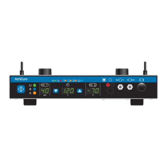
Page 14: Acm Front Panel - Illustration And Nomenclature
2.2. ACM Front Panel – Illustration and Nomenclature An illustration of the ACM front panel is shown in Figure 2, below. Figure 2 – ACM Front Panel Ablation Activation Switch Ablation Timer Increase Button Ablation Status Indicator Handpiece Probe Temperature O Gas Gauge Display Handpiece Thermocouple Port System Status Indicator... - Page 15 Indicator Symbol Description READY – Green LED This status indicates the ACM is in stand-by mode and is ready to start the cryo ablation cycle. FREEZE – Blue LED This status indicates the ACM is in cryo freeze state and the N O gas is allowed to flow through the Handpiece causing drop in probe temperature.
- Page 16 2.2.2. System Status Indicators There are six system status indicators on the front panel of the ACM: SYSTEM POWER, SYSTEM FAULT, MAINTENANCE NEEDED, LOW CYLINDER PRESSURE, CYLINDER HEATER BAND ACTIVE, and FOOTSWITCH ACTIVE. These indicators are described below. Figure 4 – ACM Status Indicators...
- Page 17 Indicator Symbol Description SYSTEM POWER – Green LED This status indicates system logic power for the ACM is available. SYSTEM FAULT – Red LED This status indicates ACM has encountered a system fault condition and has halted all operation. The ACM unit will not operate until the fault condition has been addressed.
- Page 18 Indicator Symbol Description LOW CYLINDER PRESSURE – Amber This status indicates the N O cylinder gas pressure into the ACM unit is below (initial system power up) or is dropping below (during usage) the optimal operating level. Two LED indication modes are available. Initial Power Up: Constant: Indicates the cylinder pressure is still...
- Page 19 2.2.3. Front Panel Functions Item Description HANDPIECE THERMOCOUPLE Receptacle This 2-pin receptacle accepts the AtriCure Handpiece thermocouple connectors. This connection is patient-isolated. HANDPIECE ELECTRONIC INTERFACE Receptacle This 14-pin receptacle is reserved for future release of AtriCure Handpiece. This connection is patient-isolated.
- Page 20 Item Description HANDPIECE PROBE TEMPERATURE ADJUST Knob This control knob provides the operator with the ability to adjust the terminal temperature of the handpiece probe. Turning the knob in the counter-clockwise rotation lowers the probe temperature, while turning the knob in clockwise rotation raises the probe temperature.
-
Page 21: Acm Rear Panel - Illustration And Nomenclature
4. Footswitch Receptacle 8. Input Voltage Selector Switch Note: Input Voltage Level Switch is factory set and is covered by unit model label. The switch and the label should not be tampered with or changed except by authorized AtriCure personnel. - Page 22 2.3.1. Rear Panel Functions Item Description Power Entry Module – This module contains both the ON/OFF switch and the wall receptacle mains fuses. Fuse Box – The Fuse Box contains fuses selected for the input voltage. See Technical Specifications in Section 7 of this manual. Cylinder Heater Band Receptacle –...
- Page 23 CLOSED prior to performing this task. Equipotential Terminal – This terminal provides a means of securely linking the earth ground of the AtriCure ACM unit to other grounded equipment. This terminal is accessible during any position of normal use and minimizes risk of accidental disconnection.
-
Page 24: Installing The Acm
Refer to hospital procedures or local codes for detailed information. 3.2.2. The ACM unit may be placed together or stacked with other AtriCure capital equipment such as the ASU, ASB, and the ORLab. However, care must be taken... -
Page 25: Installing Cylinder Heater Band
NOTE: If the nitrous oxide cylinder is too large or too small for the supplied ACM Heater Band to fit securely, contact AtriCure Customer Support for replacement. Figure 6 – Cylinder Heater Band Installation... -
Page 26: Installing N O Gas Line Hose
If physical damage is found do not use the N O Gas Line Hose and contact AtriCure for replacement. NOTE: Refer to the ACM Tank Hose Subassembly Cart Attachment Instruction (P000862) for details on securing the N O Gas Line Hose Module to the AtriCure System Cart. - Page 27 • Align the quick-connect gas connector from the gas hose line with the ACM O inlet port. • Insert and push in the connector until you hear it “click” in place and the connection is fully seated and secured from unlatching. •...
-
Page 28: Installing N O Exhaust Hose
• Hand tighten the connection and verify there is no leak when cylinder valve is opened. • If a leak is detected, tighten the hand knob connection further. A wrench may be needed to tighten the connection. • If the leak cannot be eliminated, either the N O gas line hose or the N O gas cylinder may need to be replaced. -
Page 29: Connecting And Disconnecting The Handpiece
Figure 9 – Connecting the N O gas line hose and N O exhaust hose to the ACM 3.8. Connecting and Disconnecting the Handpiece • Connect the Handpiece directly to the ACM. • Insert the Handpiece pneumatic interface connectors into the pneumatic receptacles on the front panel of the ACM, ensuring that each pneumatic inlet and exhaust connection is fully seated and secured. - Page 30 Figure 10 – Connecting the Handpiece to the ACM...
-
Page 31: Instructions For Use
Instructions For Use 4.1. Powering Up the ACM 1. Ensure that the ACM has been plugged into a proper hospital power receptacle. NOTE: Do not use extension cords or three-prong to two-prong adapters where applicable. The power cord assembly should be periodically checked for damaged insulation or connectors. -
Page 32: Operating Modes
4.2. Operating Modes The ACM operates in one of five modes: READY, FREEZE, DEFROST, ERROR and FAULT modes. These modes are identified by the system status indicator LEDs and the ablation status indicator LEDs located on the front of the ACM unit. See Figure 11, below. - Page 33 NOTE: Handpiece probe temperature may drop temporarily during depressurization phase (transition from Defrost to Ready state). 4.2.4. ERROR Mode – This Mode is entered upon detection of any recoverable error conditions during any Mode excluding the FAULT Mode. The ACM unit will display the corresponding error message when in READY Mode, and may halt operation temporarily upon detection of the error condition.
-
Page 34: Delivering Cryo Energy
4.3. Delivering Cryo Energy 4.3.1. Connect the Handpiece, Pneumatics, Cylinder Heater Band, and Footswitch Connect the Handpiece, N O Gas Line Hose, N O Exhaust Hose, Cylinder Heater Band, and Footswitch as described in Sections 3.4. through 3.8., and note no errors are indicated by the ACM unit. - Page 35 Figure 12B – ACM Indicating Missing Handpiece 4.3.2. Position the Handpiece To position the Handpiece, follow the Instructions for Use provided with the Handpiece. 4.3.3. Delivery of Cryo Energy 1. To start the cryo ablation cycle, simply press and release the Ablation Activation Switch or the Footswitch.
- Page 36 5. At this point, the ACM unit can be made to transition into one of two modes depending on the ACM model: Freeze Mode or Ready Mode. International – ACMs Defrost to Ready: Press and release the Ablation Activation Switch or the Footswitch. The ACM unit vents and depressurizes the handpiece.
- Page 37 4.3.4. Powering down the ACM Upon completion of the procedure, the ACM unit can be powered down. NOTE: Verify that the ACM unit is in the Ready Mode prior to powering down the unit. If the unit is not in the Ready Mode, cycle the ACM by continuously pressing the Ablation Activation Switch or the Footswitch until the unit returns to the Ready Mode.
-
Page 38: Parameter Entry Mode / Adjusting The System Default Parameter Values
4.4. Parameter Entry Mode / Adjusting the System Default Parameter Values 1. Power up the ACM unit. The system will go through its Power On Self Test (POST) routine. 2. Upon completion of POST, press and hold down the Ablation Activation Switch for approximately three seconds and release. -
Page 39: Troubleshooting
If a fault condition should occur, the N O Gas Gauge display on the front panel will display the following fault code. Contact AtriCure Customer Service for support. NOTE: The ACM will be unusable until the P-Error is resolved. DISPLAY... -
Page 40: Acm Error Codes
NOTE: The ACM will remain usable while displaying an E-Error DISPLAY DESCRIPTION SOLUTION MESSAGE System Controller Board Error – Fuse Contact AtriCure Customer Service blown for support System Controller Board Error – Triac Contact AtriCure Customer Service inoperative for support... - Page 41 ACM back on, • Powering down ACM before fully depressurizing the handpiece, or If problem persists, contact AtriCure • Leaking Inlet Valve Customer Service for support. Note: User may be unable to connect For ACMs WITHOUT an “L”...
-
Page 42: Handpiece Error Codes
Connect Handpiece Handpiece Not Connected. Thermocouple Connection READY Mode Only Replace Handpiece. Defective Thermocouple. If Problem Persists, Contact AtriCure Customer Service. READY Mode Only Replace Handpiece. Defective Thermocouple. If Problem Repeats, Contact AtriCure Customer Service. FREEZE and DEFROST Mode Only Replace Handpiece. -
Page 43: Symbols Used
Symbols Used Attention: consult accompanying documents Dangerous Voltage Power OFF Power ON Alternating Current Fuses Equipotential Terminal Type CF Applied Part Start READY FREEZE DEFROST Gas Gauge (Time Remaining) Timer... - Page 44 Timer Decrease Button Timer Increase Button Probe Temperature Connector Gas Inlet Gas Outlet Temperature Adjust Gas Exhaust Power Maintenance Needed Low Gas Pressure...
- Page 45 Cylinder Heater Band Footswitch Maximum Pressure Follow instructions for use...
-
Page 46: Technical Specifications
• Storage and Transit temperature: –35°C to +54°C • Humidity: 15 to 90% relative humidity 7.3. Electrical Specifications • ACM1: 100-120VAC, (115 VAC nominal), 50/60 Hz • ACM2: 220-240VAC, (230 VAC nominal), 50/60 Hz 7.4. Mains Fuses • 100 -120VAC, 50 / 60 Hz,: Replace fuses as marked: 4.0A/250V, T-lag, 5 ×... -
Page 47: Preventive Maintenance And Cleaning Of Acm
Visually inspect the footswitch for fluids or other infectious hazards. Clean as necessary using the instructions in Section 8.2. The ACM does not have any customer serviceable parts aside from mains fuses, gas line desiccant filter, and Inline gas filter element. For servicing issues, contact AtriCure, Inc. at: 7555 Innovation Way... -
Page 48: Cleaning And Disinfecting
7. If soil remains on the white cloth, repeat steps 3 through 6. 8. After cleaning is complete, turn the unit on to perform Power On Self-Test (POST). If any errors are received, contact AtriCure to begin return process. -
Page 49: Servicing Of Acm Unit
C002261 9.1.2. Procedure The ACM unit has been pre-set at the factory to either 110V – 120V (ACM1) or 220V – 240V (ACM2). The Rating Label below the Power Entry Module on the back panel of the ACM indicates the selected Input Voltage for this unit. This setting should only be adjusted by the manufacturer or by an authorized AtriCure technical service representative. -
Page 50: Inspection And Replacement Of In-Line N
Inspection and Replacement of In-Line N O Filter 9.2.1. Tools and Parts • 3/32 inch Allen Wrench • 1.0 inch hex Socket • Socket Wrench • Filter: In-Line N AtriCure Type Manufacturer Part Number Filter Filter C002458 TF Series Swagelok... - Page 51 3. Using the 1 inch (25 mm) hex Socket, loosen the filter bonnet nut (Note: snap ring does not need to be removed). 4. Visually inspect the outer surface of the filter element for an accumulation of debris. If more than half of the outer surface is coated with debris proceed to step 5 to replace the filter element, otherwise insert the Filter Element into the housing, verify the filter gasket is in position and thread the Filter Bonnet Nut tight onto the housing proceed to step 7.
-
Page 52: Replacement Of Gas Line Desiccant Filter And Tip Washer
9.3. Replacement of Gas Line Desiccant Filter and Tip Washer 9.3.1. Parts • Replacement parts: Item Supplied By Part Number Filter Cartridge AtriCure F021720 Filter O-ring AtriCure F010924 O-ring lubricant AtriCure C002502 US Tank Hose Assembly... - Page 53 Note: There are two filter cartridge housing. Make sure servicing of the filter cartridge is performed only on the unit next to the pressure gauge as shown in the figure below. 2. Remove the desiccant filter cartridge by rotating it counter-clockwise. Refer to the figure below.
-
Page 54: Other Replacement Components
A000728 Cylinder Heater Band (CMH22) AtriCure A000727 AC Power Cord – 10 ft (USA) AtriCure C000262 NOTE: Standard cylinder size for the AtriCure Cart is 20lbs with a CGA326 valve. 9.4.2. International Item Supplied By Part Number ACM Footswitch AtriCure A000708 O Gas Line Hose Assembly (2.5ft /... -
Page 55: Accessories
Cylinder heater band with dimensions of 12 inch x 22 inch (30.5 cm x 55.9 cm). Spring Extension Kit is available for larger diameter cylinders – contact AtriCure customer service 10.3. CMF1, Cryo Module Footswitch Momentary contact, pedal switch with 15 feet signal cord which can be used in place of the Ablation Activation Switch at the ACM front panel. - Page 56 (1) adversely affected due to use with devices manufactured or distributed by parties not authorized by AtriCure, Inc. (2) repaired or altered outside AtriCure’s factory in a way so as to, in AtriCure’s judgment, affect its stability or reliability, (3) subjected to improper use, negligence or accident, or (4) used other than in accordance with the design and use parameters, instructions and guidelines for the product or with functional, operational or environmental standards for similar products generally accepted in the industry.
Need help?
Do you have a question about the ACM1 and is the answer not in the manual?
Questions and answers