
Related Manuals for corob D300


Summary of Contents for corob D300
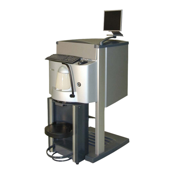
- Page 1 COROB D300 Automatic dispensing machine Service and Maintenance Version 1.0 RA(2005)
- Page 2 CPS Color Equipment Oy COROB D300 Service and Maintenance manual Version 1/05 © COPYRIGHT 2005, CPS Color Equipment Oy All rights reserved Copying and editing this material in any way (e.g. saving and photographing it) is forbidden without explicit written permission from CPS Color Equipment Oy.
-
Page 3: Table Of Contents
TABLE OF CONTENTS 1 GENERAL ........................2 1.1 COROBTM D300 parts..................2 1.2 The control system of COROB D300 ..............4 1.3 Technical information ..................8 2 MACHINE INSTALLATION ..................10 2.1 Installation site requirements ................10 2.2 Installation ...................... 10 2.3 Mounting monitor cables .................. -
Page 4: General
1.1 COROB D300 parts COROB D300 is an automatic dispensing machine available with sixteen colourant canisters. The canister size is four or six litres. COROB D300 is meant for dispensing water-based colourants and its main operational utilisation is for all kinds of shops and other institutions. - Page 5 1 - General Main mechanical parts Figure 3: Parts of the upper frame: Rack for canisters Colorant canisters Dispensing module Valves Interface board C Figure 2: Main assemblies: Foot Upper frame Can table Puncher O r d e r o f t h e pu m ps a n d h o se s Figure 4: Fixing order of the hoses and numbering of pumps and canisters is marked in above picture.
-
Page 6: The Control System Of Corob
Interface board A Nozzle 10. Cable interface 1.2 The control system of COROB D300 The COROB D300 is controlled by processor board, which controls COROB D300’s motors through the connector board. PULSE ZERO RS232 Figure 6: The control system of COROB... - Page 7 The sensors are connected to the connector board that transmits information to the processor board and to the PC. All boards that are in the COROB D300 are shown in figure 7. The order code for each board is after the name of the board in table 3. Figure 7: Boards of COROB D300 Table 3.
- Page 8 1 - General The COROB D300 has three interface boards: A, B and C. The boards A and B are for controlling solenoids. The solenoid board A that controls the valves is in front of the dispensing module, in the lower part of it, see number 8 in figure 5.
- Page 9 This solenoid is beside the air pump in the dispensing module, number six in figure 5. Se nsor s The sensors in the COROB D300 are used for • monitoring if the humidifier cap is under the nozzles or not, (CUP) •...
-
Page 10: Technical Information
Piston pumps: only the piston of the pump in use is moving Dispensing parameters • Fluid Ounce: US (29.57ml) or metric (31.24ml) • Smallest unit size: 1/384Fl.oz • Accuracy: ± 1%, with shots greater than 1ml Specifica tions • Water and glycol based and non-VOC colourants COROB D300... - Page 11 1 - General M o t o r s • Dispensing motor location: in front of the machine, see figure 5 on page 4. • Stirring motors location: under each canister, see figure 13. Figure 13: The impeller in every canister has an own stirring motor.
-
Page 12: Machine Installation
WARNING! Only a service representative authorised by the supplier may install the machine. The COROB D300 is delivered packed in a wooden crate that, in addition to the dispensing machine, contains an equipment package and all the ordered optional parts 2.1 Installation site requirements... - Page 13 This means that equipment that got their power through the COROB D300’s connecting plate, like the air pump, monitor or computer, are not switched off. Install the cables of monitor, keyboard and mouse, if necessary. The instruction is in the manual folder which is delivered in the accessory kit.
- Page 14 Figure 16: The humidifier cap is under the nozzles. 21. Fill in the Installation report and Warranty registration form and send it to CPS Color Equipment Oy. NOTE!: The warranty becomes valid after installation. However, this will never exceed 14 months from the delivery. COROB D300...
-
Page 15: Mounting Monitor Cables
2 - Machine installation 13 2.3 Mounting monitor cables Procedur e Lift up the monitor arm and corner frame, figure 17. Pass two protective hoses, length 450 mm, around the monitor cables as shown in figure 18. Figure 17: The monitor arm and corner Figure 18: Two protective hoses, violet ones, frame are lifted up. -
Page 16: Mounting The Keyboard And The Mouse Cable
Figure 23: Fasten both the mouse cable and Figure 24: Put the front casing and panel the keyboard cable to the mounts with cable back in place. Fasten the keyboard with ties. stickers on top of the casing. COROB D300... -
Page 17: Maintenance Instructions
MAINTENANCE INSTRUCTIONS WARNING! Before service, repairs and cleaning, unplug the mains from the outlet. 3.1 Removing the front casing The COROB D300’s dispensing module is protected with a front casing. You can remove this casing only for service. Tools required: •... -
Page 18: Tilting The Dispensing Module
2.5 mm Allen key Procedur e: Switch off the COROB D300 and unplug the mains cable from the outlet. Remove front casing, see instructions on page 15. Remove the hydraulic can table, see “3.2 Removing the can table during service”. -
Page 19: Changing The Solenoid Rail Assembly
3 mm Allen key Procedur e Switch off the COROB D300 and unplug the mains cable from the outlet. Remove front casing, see instructions on page 15. Remove the hydraulic can table, see “3.2 Removing the can table during service”. -
Page 20: Adjusting The Valve Solenoid
35. Also the solenoid coil moves upwards. Tighten the solenoid to this location with screws. Figure 34: Place a tool under the plunger. Figure 35: Push the plunger upwards until the draft bar touches the outlet of the pump (white arrow). COROB D300... -
Page 21: Changing The Puncher Blade (Optional)
3 - Maintenance instructions 3.6 Changing the puncher blade (optional) The colorant spray coming from the nozzles must hit the middle of the hole in the can’s cover. WARNING! The punching blade may cause personal injury. Be careful when working with the blade. Tools required: •... -
Page 22: Maintenance Of The Hydraulic Lift Unit
Procedur e: Switch off the COROB D300 and unplug the mains cable from the outlet. Remove the hydraulic can table, see “3.2 Removing the can table during service”. Remove the cover behind the table (six screws: four in upper part and one on both sides below). - Page 23 3 - Maintenance instructions Figure 40: Removing the back cover. Remove the retaining ring from the shaft in the upper part of the pump, figure 41. Remove the filter from top of the pump and replace it with a plug to prevent the oil leaking out.
- Page 24 NOTE! Check that there is about 1 cm gap in the movement of the lower pedal <=> a few millimetres gap in connecting rod. Place the shaft in position in top of the pump. Place the retaining rings in position. COROB D300...
-
Page 25: Venting
If the hydraulic can table doesn't maintain it's position, there is probably air in the hose and/or in the cylinder. The air can be removed according to the following instructions. Procedur e: Remove the can table from the COROB D300. Lift the can table to the upper position. -
Page 26: Adding Oil
3.7.3 Adding oil If COROB D300 has for example fallen during transport, the oil in the cylinder and pump may have leaked out. In this case you must add oil to the unit. Installation oil: Mobil Oil Light ISO VG 32 Tools required: •... -
Page 27: Replacing A Pump
3 - Maintenance instructions 3.8 Replacing a pump Every colorant has its own pump in the COROB D300. The pumps have NBR O-rings. The pumps are numbered from right to left, see figure 50. You can also see the numbering of the canisters in that same figure. -
Page 28: Removing A Pump
NOTE!: Place some paper or cloth under the pump and over the foot’s cover plate to keep the machine clean. The cover plate is very difficult to change! 3.8.1 Removing a pump Switch off the COROB D300 and unplug the mains cable from the outlet. Remove front casing, see instructions on page 15. Remove the humidifier cap. -
Page 29: Installing A Pump
10. Check that the nozzle hose is not clogged after the installation because a clogged hose can damage the pump. 11. Place the can table back in position, if needed. 12. Switch on the COROB D300. 13. Dispense 150 millilitre colorant to fill up the hoses. -
Page 30: Replacing A Canister
(A). The other screw goes in position B. 3.9 Replacing a canister Replace one canister at time so the canister order does not change. You can see the canister order in figure 50 on page 25 and a label attached inside the COROB D300’s cover. COROB... -
Page 31: Removing A Canister From The Machine
3.9.1 Removing a canister from the machine Procedur e Switch off the COROB D300 and unplug the mains cable from the outlet. Remove front casing, see instructions on page 15. Remove the corner frame on that side where you change a canister. -
Page 32: Installing A Canister
Place the canister over the rack for canisters and lower it in position. Fasten the hose into the pump: Push the hose into pump’s suction side. Place the special tool between the tap and it’s sleeve and push the sleeve outwards from the valve. COROB D300... - Page 33 Thread the hooks into the holes in the side plate Lower the back panel down Put the cover in position. Place the corner frame in place. Switch on the COROB D300. 10. Dispense 150 millilitre of colorant from the new canister to fill in the hoses.
-
Page 34: Replacing A Sensor
COROB D300’s can on can table sensor is a infrared (IR) sensor that consists of two parts: trans- mitter (B in figure 72) and receiver (A in figure 72). The sensor is on the top of the can table on both sides of it. -
Page 35: How To Check The Functioning Of The Ir Sensors
3 mm Allen key Procedur e: Switch off the COROB D300 and unplug the mains cable from the outlet. Remove front casing, see instructions on page 15. Remove the processor board by pulling it carefully away from the connector board. -
Page 36: Replacing A Motor
3.12 Replacing a motor The COROB D300 has two different kind of motors: the other type is for stirring and the other for dispensing. 3.12.1The dispensing motor The dispensing motor is behind the front cover. The motor is screwed into the motor bedstead, which is attached with four screws to the motion plate. - Page 37 3 - Maintenance instructions Remove the front casing according to instructions on page 15. Remove the can table, see “Removing the can table during service” on page 15. Disconnect the hoses from the angle joints of the water reservoir holder. Remove the reservoir’s holder which is fixed with two M8 screws to motor bedstead.
- Page 38 Fa st ening the di spensing motor Procedur e: Fasten the dispensing motor to the motor bedstead. Make sure that the actuator’s shaft is seen throw the hole behind the dispensing module. COROB D300...
-
Page 39: The Stirring Motors
D300 22. Test the pulse and the 0 sensors: (Koecdriver: D300 tests, see “Encoder and zero sensor test” on page 45) 3.12.2The stirring motors There is a stirring motor under each colorant canister. You need to change the stirring motor if stirring is not working. - Page 40 3 - Maintenance instructions Procedur e: Switch off the COROB D300 and unplug the mains cable from the outlet. Remove the protective cover from top of the canisters. Open two screws on top and remove the back panel. Remove side plates.
-
Page 41: Service Operations
4 - Service operations SERVICE OPERATIONS Check following items during every service call, however at least once a year: • Hoses Check the colorant hoses and their fastenings. Change a leaking hose to a new one. • Stirring mechanism Check that all the impellers are working correctly. •... -
Page 42: Essential Error Codes
The can on can table sensor informs, that there is no can on can table during dispensing. Operating method: The COROB D300 checks that the ‘can on can table’ sensor (IR sensor) is activated during dispensing. This ensure that you do not dispense without having a can under the nozzles. Occurrences: A can is missing or it is placed with negligence on the can table and the sensor is not activated. -
Page 43: Error Code 8197: Crc Error On Data Receive
The nozzle closer sensor informs that the nozzle closer is not open during dispensing. Operating method: The COROB D300 checks that the nozzle closer is open during dispensing. This is used to prevent dispensing into the nozzle cup. In the beginning of dispense the movement of the dispensing motor is connected with cup solenoid for a specific pulse period to open the nozzle cup with the lever mechanism. -
Page 44: Electrical Diagram
6 - Electrical diagram ELECTRICAL DIAGRAM Figure 85: The electrical diagram of the COROB D300 with sixteen canisters. COROB D300... - Page 45 IR ABSENDERKARTE SA 814.V1 V06271 IR VASTAANOTINKORTTI IR RECEIVER BOARD IR ABNEHMERKARTE SA 815.V2 V43770 MOOTTORI (ANNOSTELU) MOTOR (DISPENSING) MOTOR (DOSIERUNG) COROB PART NO: 1M2-614-01 V43803 VIRTALÄHDE POWER SUPPLY STROMVERSORGUNG MEAN WELL SP-200-24 V43771 SOLENOIDI SOLENOID SOLENOID 142-08A62XX SMO-0837L9.8CJ V45099 PYSÄYTYSKYTKIN KP...
- Page 46 V45093 MAADOITUSKAAPELI GROUND CABLE ERDUNGSKABEL +24 V V45094 SUOJAMAADOITUSKAAPELI PE-GROUND CABLE SCHUTZLEITUNG +24 V V45095 SUOJAMAADOITUSKAAPELI PE-GROUND CABLE SCHUTZLEITUNG V45096 SUOJAMAADOITUSKAAPELI PE-GROUND CABLE SCHUTZLEITUNG QUAD BLOCK V45097 SUOJAMAADOITUSKAAPELI PE-GROUND CABLE SCHUTZLEITUNG V43890 ILMAPUMPPU AIR PUMP LUFTPUMPE ELITE 799 COROB D300...
-
Page 47: Koecdriver
Below program functions are described one by one. 7.1 Tests 7.1.1 Serial test First natural function to test is the serial communication between the PC and the COROB D300. Check that you have connected serial line cable from the PC COM1 (or some other defined com port) to machine and run the test. -
Page 48: Stirring Tests
D300 is stirring colorants automatically using predefined stirring param- eters, normal setup for the COROB D300 is like 1 minute of stirring in hour for each colorant. Note that there are separate stirring motors for each canister, also the active stirring times can be different for each canister. -
Page 49: Purge, Init And Dispense Commands
7 - Koecdriver Basically you can disable cup and can sensors, if not present or not working. You can also setup the stirring time and stirring pause intervals for all colorants, Write button updates selected setting to machine, Read button reads and creates a report about parameter values read from the machine. - Page 50 Formula 1 2 3 4 means 2 millilitres (ml) from canister number 1 and 4 mls from canister number 3. NOTE!: You can run the formula more than once by putting Number of dispenses field value bigger than 1. COROB D300...
- Page 51 COROB D300-16/SR COROB D300-24/SR Automaattinen sävytyskone Automatic dispensing machine Die automatische Abtönmaschine Varaosat * Spare Parts * Ersatzteile Version 1.0 RC (2007)
- Page 52 CPS Color Equipment Oy COROB D300 Varaosat * Spare Parts * Ersatzteile Version 1/07 © COPYRIGHT 2007, CPS Color Equipment Oy Kaikki oikeudet pidätetään Tämän materiaalin kaikenlainen kopioiminen ja muuttaminen millään keinoin (esim. tallentamalla ja valoku- vaamalla) on kielletty ilman CPS Color Equipment Oyn kirjallista lupaa.
- Page 53 Wenn die Teile (die Nummer is blau) ist markt als , finden Sie eine Verbindung zu dem Unterzusammenbau. Wenn die Teile is markt als (gelbe Dreieck), gehört diese Teile zu der COROB D300 SR Maschine. Ein Bestell- und ein Retourenformular für Ersatzteile finden sich am Ende des Katalogs.
- Page 54 Varaosakirjan käytöstä ...................... i Use of the spare part manual ..................... i Benutzung des Ersatzteilverzeichnisses ................i V44425 COROBTM D300-16/SR................... 2 V44423 Jalka kp ..Foot assy ..Fusszus............... 4 V44631 Ylärunko kp ..Upper frame assy ..Oberrahmenzus........6 V44992 &...
- Page 55 2 V44425 COROBTM D300-16/SR ver 1.0 2007 V44425 COROB D300-16/SR COROB D300...
-
Page 56: V44425 Corobtm D300-16/Sr
1.0 2007 V44425 COROBTM D300-16/SR V44425 COROB D300-16/SR Koodi Spesifikaatio (sivu) Code Part Part Specification (page) Code Spezifikation (Seite) JALKA KP FOOT ASSY FUSS ZUS. YLÄRUNKO KP UPPER FRAME ASSY OBERRAHMEN ZUS. V44640 ALALEVY LOWER PLATE UNTERE PLATTE V44453... -
Page 57: V44423 Jalka Kp
1.0 2007 V44423 Jalka kp ..Foot assy ..Fusszus. COROB D300... - Page 58 SF 3817M10 40 I S V44687 POHJALEVY BASE PLATE BODENPLATTE V44504 TUKILEVY SUPPORT PLATE STÜTZPLATTE KUUSIOKOLORUUVI ALLEN SCREW INNEN-6-KT-SCHRAUBE M8 x 70 8.8 Zn DIN 912 LUKITUSMUTTERI LOCKING NUT SICHERUNGSMUTTER M8 DIN 985 KUUSIOKOLORUUVI ALLEN SCREW INNEN-6-KT-SCHRAUBE M10 x 35 DIN 912 COROB D300...
-
Page 59: V44631 Ylärunko Kp
1.0 2007 V44631 Ylärunko kp ..Upper frame assy ..Oberrahmenzus. COROB D300... - Page 60 Säiliö - Pumppu Canister - Pump Behälter - Pumpe V45345 ASENNUSTYÖKALU FITTER'S TOOL INSTALLATIONSWERKZEUG FOR JOHN GUEST FITTINGS LETKU HOSE SCHLAUCH FEP ID 5/8" x OD 3/4", Ø15,88/ V46220 Säiliö - Pumppu Canister - Pump Behälter - Pumpe Ø19,05 COROB D300...
-
Page 61: V44992 & V45166 Pastasäiliö Kp
1.0 2007 V44992 & V45166 PASTASÄILIÖ KP ..COLORANT CANISTER ASSY ..PASTENBEHÄLTERZUS. COROB D300... - Page 62 4 L ASSEMBLY (NOT LID AND V45223 PASTASÄILIÖ COLORANT CANISTER PASTENBEHÄLTER MOTOR) 6 L ASSEMBLY (NOT LID AND V45226 PASTASÄILIÖ COLORANT CANISTER PASTENBEHÄLTER MOTOR) V45205 KANNAKE SUPPORT KONSOLE V45218 PT-RUUVI PT-SCREW PT-SCHRAUBE 50 x 12 PZ ZN 1442 COROB D300...
-
Page 63: V44494 Annostelumoduuli Kp
1.0 2007 V44494 ANNOSTELUMODUULI KP ..DISPENSING MODULE ASSY ..DOSIERMODULZUS. COROB D300... - Page 64 (Bedienungstafel + Druckknopf mit painike + kaapeli) + cable) licht + Kabel) V44752 LIITINKORTTI CONNECTOR BOARD SCHNITTSTELLENKARTE D300CON-A.1 V43786 PROSESSORIKORTTI PROCESSOR BOARD PROZESSORKARTE V44249 SOLENOIDIKISKO KP SOLENOID RAIL ASSY SOLENOIDSCHIENEZUS. (23) KUUSIOKOLORUUVI ALLEN SCREW INNEN-6-KT-SCHRAUBE M4 x 8 DIN 7991 10.9 COROB D300...
- Page 65 NOZZLE CLOSER ASSY DÜSENSCHLIESSER ZUS. (31) OLD VERSION V44965 SUUTIN KP NOZZLE ASSY DÜSE ZUS. (33) V44871 TIPPAKUPPI DROP CATCHER TROPFENFÄNGER KOSTUTUSLETKU HUMIDIFYING HOSE BEFEUCHTUNUNGSSCHLAUCH V04006 PVC 4/7MM vesisäiliöltä suuttimille from reservoir to nozzles von Reservoir zu Düsen COROB D300...
-
Page 66: V45020 Käyttölevy Kp
1.0 2007 V45020 Käyttölevy kp ..Motion plate assy ..Abtriebblattzus. COROB EXACT... - Page 67 ALLEN SCREW INNEN-6-KT-SCHRAUBE M3 x 6 DIN 912 V43967 KÄYTTÖVIPU KP ACTUATOR ASSY ABTRIEBHEBEL ZUS. V44657 VETOTANKO DRAFT BAR ANGRIFFSTANGE V43712 LIERIÖSOKKA CYLINDRIC PIN ZYLINDERSTIFT Ø3; L=30; DIN 7 A2 V41814 KORTTIKIINNIKE BOARD BRACKET KARTEBEFESTIGUNG RICHCO LCBS 401 / COROB D300...
-
Page 68: V46410 Pumppulohko Kp
1.0 2007 V46410 Pumppulohko kp ..Pump block assy ..Pumpenblockzus. COROB EXACT... - Page 69 1442 ZN PZ 3,5 x 8 V45563 ANNOSTELUPUMPPU KP DISPENSING PUMP ASSY DOSIERPUMPE ZUS. VITON WITH BLACK LEVER V46219 ANNOSTELUPUMPPU KP DISPENSING PUMP ASSY DOSIERPUMPE ZUS. FFKM WITH YELLOW LEVER V43711 TAKALEVY BACK PANEL ENDBLECH VETONIITTI RIVET NIET Ø4 x 8 COROB D300...
-
Page 70: V43649 Annostelunokka Kp
1.0 2007 V43649 Annostelunokka kp ..Dispensing cam assy ..Kolbenheberzus. COROB EXACT... - Page 71 MUTTERI MUTTER M6x10x1 WÜRTH 9276 610 14 6 V43639 ANNOSTELUPALKKI BALKEN 7 V43632 AKSELI SHAFT ACHSE 8 V43651 VETOHOLKKI WITHDRAWAL SLEEVE ABZIEHHÜLSE VARMISTINRENGAS RETAINING RING SICHERUNGSRING 19 x 1.2 DIN 471 NIITTI RIVET NIETE Ø3.2 x 8 STEEL COROB D300...
-
Page 72: V44517 Annostelumoottori Kp
1.0 2007 V44517 Annostelumoottori kp ..Dispensing motor assy ..Dosiermotorzus. COROB EXACT... -
Page 73: V43759 Moottori Kp
ZERO SENSOR NULLSENSOR ZERO KUUSIOKOLORUUVI ALLEN SCREW INNEN-6-KT-SCHRAUBE M6 x 12 DIN 912 KUUSIOKOLORUUVI ALLEN SCREW INNEN-6-KT-SCHRAUBE M4 x 6 DIN 912 KUUSIOMUTTERI HEXAGON NUT 6-KT-MUTTER M8 DIN 934 KUUSIOKOLORUUVI ALLEN SCREW INNEN-6-KT-SCHRAUBE M8 x 20 DIN 912 8.8 COROB D300... - Page 74 V43759 Moottori kp ..Motor assy ..Motorzus. COROB EXACT...
- Page 75 V43759 Moottori kp ..Motor assy ..Motorzus. Koodi Spesifikaatio (sivu) Code Part Part Specification (page) Code Spezifikation (Seite) V43770 MOOTTORI MOTOR MOTOR COROB PART NO: 1M2-614-01 V43766 KOTELO CASING BUCHSE V43769 PULSSIANTURI PULSE SENSOR PULSSENSOR PULS V43765 KANSI COVER...
-
Page 76: V44249 Solenoidikisko Kp
1.0 2007 V44249 Solenoidikisko kp ..Solenoid rail assy ..Solenoidschienezus. COROB EXACT... - Page 77 141-05B22XX SMO-0520S06AU V43757 RULLA ROLLER ROLLE SKIFFY 005 4205 000 02 KUUSIOKOLORUUVI ALLEN SCREW INNEN-6-KT-SCHRAUBE M4 x 8 DIN 912 V44844 LIITYNTÄKORTTI INTERFACE BOARD ANSCHLUSSKARTE D300B-A.1 V43830 LÄPIVIENTI LEAD-IN EINGANG RICHCO QFG-16210 (13.5/10x2) V44836 KIINNITYSLEVY ADAPTER PLATE STELLSCHEIBE COROB D300...
-
Page 78: V46377 Suuttimensulkija Kp
1.0 2007 V46377 Suuttimensulkija kp ..Nozzle closer assy ..Düsenschliesserzus. COROB EXACT... - Page 79 M4 x 10 DIN 912 V46360 AKSELI SHAFT ACHSE V46311 SÄÄTÖRENGAS ADJUSMENT RING HALTERING JOUSISOKKA EXPANSION PIN SPANNSTIFT Ø3 x 12 DIN 1481 ALUSLEVY WASHER UNTERLAGSSCHEIBE DIN 125 KUUSIOKOLOPIDÄTINRUUVI ALLEN SET SCREW FESTSTELLSCHRAUBE M6 x 6 DIN 913 COROB D300...
-
Page 80: V46287 Suutin Kp
1.0 2007 V46287 Suutin kp ..Nozzle assy ..Düsezus. COROB EXACT... - Page 81 M4 x 10 DIN 912 KUUSIOKOLORUUVI ALLEN SCREW INNEN-6-KT-SCHRAUBE M5 x 16 DIN 912 V46255 HOLKKI SLEEVE HÜLSE V46665 SUUTINRYHMÄ KP NOZZLE GROUP ASSY DÜSEGRUPPEZUS. 24 NOZZLES V46673 SUULAKE NOZZLE DÜSE WITH MAGNETS V46706 LETKU HOSE SCHLAUCH PA11 F15 8/6 L=450MM COROB D300...
-
Page 82: V46359 Suutin Kp
1.0 2007 V46359 Suutin kp ..Nozzle assy ..Düsezus. COROB EXACT... - Page 83 SLEEVE HÜLSE V46260 KOROKEHOLKKI SPACER ERHÖHUNGSBUCHSE Ø6 / Ø3.1 x 4 V46361 SUUTIN KP NOZZLE ASSY DÜSE ZUS. VÄL V46635 TIPPAKUPPI KP DROP CATCHER ASSY TROPFENFÄNGERZUS. V45475 LETKU KP HOSE ASSY SCHLAUCH ZUS. D8/6 / D6/4 L= 450MM COROB D300...
-
Page 84: V43739 Suuttimensulkija Kp
1.0 2007 V43739 Suuttimensulkija kp ..Nozzle closer assy ..Düsenschliesserzus. COROB EXACT... - Page 85 AKSELI KP SHAFT ASSY ACHSE ZUS. ALUSLEVY WASHER UNTERLAGSSCHEIBE M5 DIN 6798 A V44191 KYTKINKAMPI COUPLING CRANK KUPPLUNGSDREHER V43771 SOLENOIDI SOLENOID SOLENOID 142-08A62XX SMO-0837L9.8CJ V44871 TIPPAKUPPI DROP CATCHER TROPFENFÄNGER V44952 KOSTUTUSSIENI MOISTENING SPONGE BEFEUCHTUNGSSCHWAMM D40 x 8 POLYESTERI PPI30 COROB D300...
-
Page 86: V44965 Suutin Kp
1.0 2006 V44965 Suutin kp ..Nozzle assy ..Düsezus. COROB EXACT... - Page 87 SPACER STUD STEHBOLZEN M3x10 971100365 URARUUVI SLOTHEAD SCREW SCHLITZSCHRAUBE M3 x 8 DIN 7985 V41051 PT-RUUVI PT-SCREW PT-SCHRAUBE 40 x 16 KA-1412 ALUSLEVY WASHER UNTERLAGSSCHEIBE DIN 9021 V45475 LETKU KP HOSE ASSY SCHLAUCH ZUS. D8/6 / D6/4 L= 450MM COROB D300...
-
Page 88: V44749 Verkkolevy
1.0 2007 V44749 Verkkolevy ..Mains connecting plate ..Anschlussblech für Netzsteker COROB EXACT... - Page 89 Part Specification (page) Code Spezifikation (Seite) V44672 VERKKOLEVY MAINS CONNECTING PLATE ANCSHLUSSBLECH FÜR NETZSTEKER V44748 KYTKIMELLINEN PISTOKE POWER ENTRY MODULE STECKER MIT SCHALTER SCHURTER V41201 PISTORASIA WALL SOCKET STECKDOSE 1,5 MM V43933 KYTKIN (SÄHK) SWITCH SCHALTER ARCOLECTRIC C1350VQ0/1BLK COROB D300...
-
Page 90: V44719 Purkkipöytä Kp
1.0 2007 V44719 Purkkipöytä kp ..Can table assy ..Dosentisch zus. COROB EXACT... - Page 91 SUPPORT ASSY KONSOLE ZUS. KUUSIOKOLORUUVI ALLEN SCREW INNEN-6-KT-SCHRAUBE M6 x 12 DIN 7991 10.9 V44967 KIINNITIN FASTENER KLEMME V44969 KIINNITYSRAUTA FIXTURE HALTEBÜBGEL KUUSIORUUVI HEXAGON SCREW 6-KT-SCHRAUBE M6 x 40 DIN 931 LUKITUSMUTTERI LOCKING NUT SICHERUNGSMUTTER M6 DIN 982 COROB D300...
- Page 92 SPACER STUD STEHBOLZEN ZN M3x 6/5 AV5.5 4971050321 V45660 JATKOMUTTERI EXTENSION NUT VERLÄNGERUNGSMUTTER SCHWINGUNGSGEDAEMPFTE MON- V42978 TÄRINÄNVAIMENNIN ANTI-VIBRATION MOUNTING 25x15 M8x35 TAGE KUUSIOKOLORUUVI ALLEN SCREW INNEN-6-KT-SCHRAUBE M8 x 20 DIN 912 8.8 V46236 TASOLEVY SURFACE PLATE PLANSCHEIBE AISI COROB D300...
-
Page 93: V44841 Lävistin Kp
1.0 2007 V44841 Lävistin kp ..Puncher assy ..Lochstanzvorrichtung zus. COROB D300... - Page 94 ALLEN SCREW INNEN-6-KT-SCHRAUBE M8 x 20 DIN 912 8.8 V45645 TULPPA PLUG STOPFEN IKH 22 18-20 S ACKURAT V46366 HALL-ANTURI HALL SENSOR HALLSENSOR PUNCHER V46333 PIDIN HOLDER HALTER FOR PUNCHING SENSOR V46336 KIINNITYSRUUVI FIXING SCREW BEFESTIGUNGSSCHRAUBE FOR MAGNET COROB D300...
- Page 95 V44841 Lävistin kp ..Puncher assy ..Lochstanzvorrichtung zus. Koodi Spesifikaatio (sivu) Code Part Part Specification (page) Code Spezifikation (Seite) V43650 MAGNEETTI MAGNET MAGNET Ø5X5 V46011 KOROTUSHOLKKI SPACER ERHÖHUNGSBUCHSE PA MU Ø8/Ø4.2 x 4 KUUSIOKOLORUUVI ALLEN SCREW INNEN-6-KT-SCHRAUBE M4 x 8 DIN 912 COROB D300...
-
Page 96: V45102 Sähkökaavio
1.0 2007 V45102 Sähkökaavio ... Electrical chart ... Schaltbild COROB EXACT... - Page 97 IR TRANSMITTER BOARD IR ABSENDERKARTE SA 814.V1 V06271 IR VASTAANOTINKORTTI IR RECEIVER BOARD IR ABNEHMERKARTE SA 815.V2 V43770 MOOTTORI MOTOR MOTOR COROB PART NO: 1M2-614-01 V43803 VIRTALÄHDE POWER SUPPLY STROMVERSORGUNG MEAN WELL SP-200-24 V43771 SOLENOIDI SOLENOID SOLENOID 142-08A62XX SMO-0837L9.8CJ V45099 PYSÄYTYSKYTKIN KP...
- Page 98 (KUPPLUNGSDREHER) OHJAUSKAAPELI CONTROL CABLE HILFSKABEL V46238 (SUUTINKUPPI) (DROP CATCHER) (KUPPLUNGSDREHER) MOOTTORIKAAPELI MOTOR CABLE MOTORKABEL V46237 (SUUTINKUPPI) (DROP CATCHER) (KUPPLUNGSDREHER) MOOTTORI MOTOR MOTOR V45162 6611001600 BUEHLER (SUUTINKUPPI) (DROP CATCHER) (KUPPLUNGSDREHER) HALL-ANTURI HALL SENSOR HALLSENSOR V46366 PUNCHER (LÄVISTYS) (PUNCHER) (LOCHSTANZ) COROB D300...
- Page 99 46 V45327 COROBTM D300-24/SR ver 1.0 2007 V45327 COROB D300-24/SR COROB D300-24...
-
Page 100: V45327 Corobtm D300-24/Sr
1.0 2007 V45327 COROBTM D300-24/SR V45327 COROB D300-24/SR Koodi Spesifikaatio (sivu) Code Part Part Specification (page) Code Spezifikation (Seite) YLÄRUNKO KP UPPER FRAME ASSY OBERRAHMEN ZUS. (50) JALKA KP FOOT ASSY FUSS ZUS. (48) PURKKIPÖYTÄ KP CAN TABLE ASSY... -
Page 101: V45352 Jalka Kp
1.0 2007 V45352 Jalka kp ..Foot assy ..Fusszus. COROB D300-24... - Page 102 UNTERLAGSSCHEIBE KUUSIOKOLORUUVI ALLEN SCREW INNEN-6-KT-SCHRAUBE M8 x 70 8.8 Zn DIN 912 LUKITUSMUTTERI LOCKING NUT SICHERUNGSMUTTER M8 DIN 985 KUUSIOKOLORUUVI ALLEN SCREW INNEN-6-KT-SCHRAUBE M10 x 35 DIN 7991 V45410 SÄÄTÖJALKA SUPPORTING FOOT TRÄGERFUSS SF 3817M10 40 I S COROB D300...
-
Page 103: V45364 Ylärunko Kp
1.0 2007 V45364 Ylärunko kp ..Upper frame assy ..Oberrahmenzus. COROB D300-24... - Page 104 Säiliö - Pumppu Canister - Pump Behälter - Pumpe V45345 ASENNUSTYÖKALU FITTER'S TOOL INSTALLATIONSWERKZEUG FOR JOHN GUEST FITTINGS LETKU HOSE SCHLAUCH FEP ID 5/8" x OD 3/4", Ø15,88/ V46220 Säiliö - Pumppu Canister - Pump Behälter - Pumpe Ø19,05 COROB D300...
-
Page 105: V45281 Annostelumoduuli Kp
1.0 2007 V45281 ANNOSTELUMODUULI KP ..DISPENSING MODULE ASSY ..DOSIERMODULZUS. COROB D300-24... - Page 106 M4 x 8 DIN 7991 10.9 KUUSIOKOLORUUVI ALLEN SCREW INNEN-6-KT-SCHRAUBE M4 x 6 DIN 912 KUUSIOKOLORUUVI ALLEN SCREW INNEN-6-KT-SCHRAUBE M5 x 10 DIN 912 V04695 KOROTUSHOLKKI SPACER ERHÖHUNGSBUCHSE PA 8/4.2 x 15 V46635 TIPPAKUPPI KP DROP CATCHER ASSY TROPFENFÄNGERZUS. COROB D300...
- Page 107 Spezifikation (Seite) V46287 SUUTIN KP NOZZLE ASSY DÜSE ZUS. (27) V46377 SUUTTIMENSULKIJA KP NOZZLE CLOSER ASSY DÜSENSCHLIESSER ZUS. WITH MOTOR (25) KOSTUTUSLETKU HUMIDIFYING HOSE BEFEUCHTUNUNGSSCHLAUCH V04006 PVC 4/7MM vesisäiliöltä suuttimille from reservoir to nozzles von Reservoir zu Düsen COROB D300-24...
-
Page 108: V45283 Käyttölevy Kp
1.0 2007 V45283 Käyttölevy kp ..Motion plate assy ..Abtriebblattzus. COROB EXACT... - Page 109 LIERIÖSOKKA CYLINDRIC PIN ZYLINDERSTIFT Ø3; L=30; DIN 7 A2 V43677 LAAKERIPESÄ BEARING HOUSING LAGERGEHÄUSE KUUSIOKOLORUUVI ALLEN SCREW INNEN-6-KT-SCHRAUBE M6 x 40 DIN 7991 10.9 KUUSIOMUTTERI HEXAGON NUT 6-KT-MUTTER M6 10.9 WULOCK V36012 RIVILIITIN TERMINAL BLOCK REIHENKLEMME SSTL 1933515-7 COROB D300-24...
-
Page 110: V46651 Pumppulohko Kp
1.0 2007 V46651 Pumppulohko kp ..Pump block assy ..Pumpenblockzus. COROB EXACT... - Page 111 PT-RUUVI PT-SCREW PT-SCHRAUBE 1442 ZN PZ 3,5 x 8 V45264 TAKALEVY BACK PANEL ENDBLECH V45563 ANNOSTELUPUMPPU KP DISPENSING PUMP ASSY DOSIERPUMPE ZUS. VITON WITH BLACK LEVER V46219 ANNOSTELUPUMPPU KP DISPENSING PUMP ASSY DOSIERPUMPE ZUS. FFKM WITH YELLOW LEVER COROB D300-24...
-
Page 112: V45272 Annostelunokka Kp
1.0 2007 V45272 Annostelunokka kp ..Dispensing cam assy ..Kolbenheberzus. COROB EXACT... - Page 113 KIINNIKE BRACKET BEFESTIGUNG MUTTERI MUTTER M6x10x1 WÜRTH 9276 610 14 V45269 ANNOSTELUPALKKI BALKEN V45731 AKSELI SHAFT ACHSE V43651 VETOHOLKKI WITHDRAWAL SLEEVE ABZIEHHÜLSE VARMISTINRENGAS RETAINING RING SICHERUNGSRING 19 x 1.2 DIN 471 NIITTI RIVET NIETE Ø3.2 x 8 STEEL COROB D300...
-
Page 114: V45278 Solenoidikisko Kp
1.0 2007 V45278 Solenoidikisko kp ..Solenoid rail assy ..Solenoidschienezus. COROB EXACT... - Page 115 141-05B22XX SMO-0520S06AU V43757 RULLA ROLLER ROLLE SKIFFY 005 4205 000 02 V44844 LIITYNTÄKORTTI INTERFACE BOARD ANSCHLUSSKARTE D300B-A.1 RICHCO QFG-16210 (13.5/ V43830 LÄPIVIENTI LEAD-IN EINGANG 10x2) KUUSIOKOLORUUVI ALLEN SCREW INNEN-6-KT-SCHRAUBE M4 x 8 DIN 912 V45277 KIINNITYSLEVY ADAPTER PLATE STELLSCHEIBE COROB D300-24...
-
Page 116: V46663 Sähkökaavio
1.0 2007 V46663 Sähkökaavio ... Electrical chart ... Schaltbild COROB EXACT... - Page 117 SOLENOIDI SOLENOID SOLENOID 142-08A62XX SMO-0837L9.8CJ V45162 MOOTTORI MOTOR MOTOR 6611001600 BUEHLER V43770 MOOTTORI MOTOR MOTOR COROB PART NO: 1M2-614-01 V43803 VIRTALÄHDE POWER SUPPLY STROMVERSORGUNG MEAN WELL SP-200-24 V43890 ILMAPUMPPU AIR PUMP LUFTPUMPE ELITE 799 V45099 PYSÄYTYSKYTKIN KP STOP BUTTON ASSY HALTEKNOPFZUS.
- Page 118 MACHINE POWER CABLE BETRIEBSKABEL #2 0V V45093 MAADOITUSKAAPELI GROUND CABLE ERDUNGSKABEL +24 V SUOJAMAADOITUSKAAPELI PE-GROUND CABLE SCHUTZLEITUNG +24 V JOHTOSARJASETTI WIRE HARNESS SET KABELSERIESET V44748 KYTKIMELLINEN PISTOKE POWER ENTRY MODULE STECKER MIT SCHALTER V41201 VERKKOLIITIN MAINS CONNECTOR NETZANSCHLUSS SCHURTER 4752 COROB D300...
- Page 119 230 V SYÖTTÖJÄNNITEKAAPELI MAIN POWER CABLE NETZKABEL QUAD BLOCK KÄYTTÖJÄNNITEKAAPELI MACHINE POWER CABLE BETRIEBSKABEL 2 24 V KÄYTTÖJÄNNITEKAAPELI MACHINE POWER CABLE BETRIEBSKABEL 1 24 V SUOJAMAADOITUSKAAPELI PE-GROUND CABLE SCHUTZLEITUNG QUAD BLOCK SUOJAMAADOITUSKAAPELI PE-GROUND CABLE SCHUTZLEITUNG SUOJAMAADOITUSKAAPELI PE-GROUND CABLE SCHUTZLEITUNG COROB D300-24...
-
Page 120: Varusteet
260 TARRAA / RULLA 260 LABELS / ROLL 260 ETIKETTEN / ROLLE TARRARULLA LABEL ROLL ETIKETTENROLLE HV3856 54x101 MM 220 TARRAA / RULLA 220 LABELS / ROLL 220 ETIKETTEN / ROLLE V45345 ASENNUSTYÖKALU FITTER'S TOOL INSTALLATIONSWERKZEUG FOR JOHN GUEST FITTINGS COROB D300... -
Page 121: Returnable Material
RETURNABLE MATERIAL Use this form when you send spare parts back to CPS Color Equipment Oy. Serial Machine Part descripition Part code number Only return Send new Repair Only return Send new Repair Only return Send new Repair Only return Send new Repair Only return... -
Page 122: Spare Parts Order
SPARE PARTS ORDER Invoice to Delivery address Delivery terms: FCA ULVILA Method of dispatch: By courier service By sea freight By airmail By air freight By truck Other ___________________________ Code Part Quantity Unit price Total Name Company Date CPS Color Equipment Oy • Tel: +358 2 6777 700 • Fax: +358 2 6777 701 • Email: service_fi@cpscolor.com...
Need help?
Do you have a question about the D300 and is the answer not in the manual?
Questions and answers