
Subscribe to Our Youtube Channel
Related Manuals for Chenbro SR113 Series


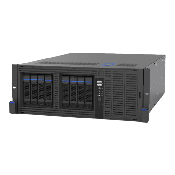
Summary of Contents for Chenbro SR113 Series
- Page 1 SR113 Series Workstation/Server Chassis User Manual July 2022 Version 0.5 A document provides an overview of product features, functions, architecture, and support specifications.
- Page 2 No license (express or implied, by estoppel or otherwise) to any intellectual property rights is granted by this document. Chenbro disclaims all express and implied warranties, including without limitation, the implied warranties of merchantability, fitness for a particular purpose, and non-infringement, as well as any warranty arising from course of performance, course of dealing, or usage in trade.
-
Page 3: Table Of Contents
SR113 Family Table of Contents Table of Contents ............................... 3 List of Figures ..............................4 List of Tables ............................... 6 Product Overview ..........................7 1-1 System Outlook Overview......................8 1-2 Security Features ........................11 1-3 Front Control Panel ........................12 1-4 Storage Configurations ...................... -
Page 4: List Of Figures
SR113 Family List of Figures Figure 1 SR113 Tower ............................8 Figure 2 SR113 4U Rackmount ......................... 8 Figure 3 SR113 Side View ..........................9 Figure 4 SR113 Front view ..........................9 Figure 5 SR113 11-slot with redundant PSU ....................10 Figure 6 SR113 8-slot with redundant PSU .................... - Page 5 SR113 Family Figure 40 Power distribution board ....................... 33 Figure 41 SR113 4U Rackmount ........................34 Figure 42 Remove top dummy cover ......................34 Figure 43 Remove foot stands ........................35 Figure 44 Ear handle installation ........................35 Figure 45 Drive tray LED identification ......................37 Figure 46 Backplane front view ........................
-
Page 6: List Of Tables
SR113 Family List of Tables Table 1 Chenbro SR113 specifications ......................7 Table 2 System environmental specifications summary ................14 Table 3 System packing information ......................15 Table 4 Product weight information ......................15 Table 5 Drive power LED/activity LED behavior ..................... 37 Table 6 Backplane specifications ........................ -
Page 7: Product Overview
The SR113 chassis has been modified to support both tool-less 3.5” HDD tray and PCI-e 3.0 slot, and transformed into feature- advanced SR107 Plus. Beneath the chassis, an information sticker reads revision and manufacturing code, necessary for technical support. Table 1 Chenbro SR113 specifications Proprietary (15.12” x 13.2”): Super Micro X11DGP-QT/X11DPX-T M/B Form Factor ... -
Page 8: System Outlook Overview
SR113 Family 1-1 System Outlook Overview Figure 1 SR113 Tower Front Bezel Lock Front Bezel (Security) Indicator Foot Stand Figure 2 SR113 4U Rackmount Ear Handle... -
Page 9: Figure 3 Sr113 Side View
SR113 Family Figure 3 SR113 Side View Side Cover (Tool-less) Side Cover Latch Figure 4 SR113 Front view 4-Bay SAS/SATA HDD module 4-Bay SAS/SATA HDD module Front Control Panel... -
Page 10: Figure 5 Sr113 11-Slot With Redundant Psu
SR113 Family Figure 5 SR113 11-slot with redundant PSU Figure 6 SR113 8-slot with redundant PSU Figure 7 SR113 8-slot with single PS2 11 PCIe slot Redundant CRPS PSU Location of rear system fan kit 8 PCIe slot ATX PS2... -
Page 11: Security Features
SR113 Family 1-2 Security Features Key lock Logo plate Figure 8 Front bezel with key lock for system security Figure 9 Intrusion switch... -
Page 12: Front Control Panel
SR113 Family 1-3 Front Control Panel Figure 10 Front control panel 1-4 Storage Configurations Figure 11 External 4-Bay and Figure 12 External 8-Bay 3.5" Figure 13 External 8-Bay 3.5" and Internal 4-Bay 3.5” HDD 8-Bay 2.5" Storage kit 5.25” Open Bay 4-Bay 3.5”... -
Page 13: Chassis Dimensions
SR113 Family 1-5 Chassis Dimensions Figure 14 Chassis dimensions 1-6 Interior view Figure 15 Chassis components 4-Bay SAS/SATA hot-swap module Fan bar Motherboard Rear 80mm system fan kit, internal Fan wall Card retainer External 80mm GPU hot-swap fan Middle 80mm fan module, hot swap Redundant CPRS module module Power distribution board... -
Page 14: System Level Environmental Specifications
SR113 Family 1-7 System Level Environmental Specifications The following table defines the system level specifications under operating and non-operating environments. Table 2 System environmental specifications summary Parameter Specification Temperature Operating 5º C to 35º C (41º F to 95º F) Temperature Non-Operating -40º... -
Page 15: System Packaging
1-8 System Packaging The original Chenbro packaging, where the server system is delivered, is designed to provide protection to a fully configured system and tested to meet ISTA (International Safe Transit Association) Test Procedure 1A. The packaging is also designed to be reused for shipment after system integration has been completed. -
Page 16: System Components Installation And Removal
SR113 Family 2. System Components Installation and Removal SR113 supports up to 8 x 3.5” hot-swap SAS/SATA HDD or 8 x 3.5” Internal SAS/SATA HDD. Support for different storage and peripheral options will vary depending on the system model and/or available accessory options installed. 2-1 Side Cover Installation Figure 16 Side cover installation Check if the thumb screws on the side cover are loosened. -
Page 17: Follow These Instructions To Remove/Install The Front Bezel Door
SR113 Family 2-2 Follow these instructions to remove/install the front bezel door Figure 17 Bezel door removal/installation Check if the key lock on the bezel door is unlocked. Press the latch on the top of the front bezel door, tilt and lift up the door. Align the hooks on the bezel door with the holes on the front panel and push it toward the chassis. -
Page 18: Follow These Instructions To Remove/Install The Front Panel
SR113 Family 2-3 Follow these instructions to remove/install the front panel Figure 18 Remove/install the front panel Remove the front bezel door. Remove the side cover. Detach the four latches and slide right the front panel. -
Page 19: Front Control Panel Maintenance
SR113 Family 2-4 Front Control Panel Maintenance Figure 19 Front control panel maintenance 2-5 3.5” Device Installation Figure 20 3.5" Device installation... -
Page 20: Storage Kit Installation (2 X 5.25" Open Bay)
SR113 Family 2-6 Storage kit installation (2 x 5.25” Open Bay) Figure 21 Guide pin location on storage kit Find screw bag #70H972200-101 (60H141230-055 *8pcs) Fix the screws on the storage kit. Figure 22 Storage kit installation 1. Press two sides of the latch of the blank to release the blank and pull the blank out. 2. -
Page 21: 4-Bay 3.5" Hot-Swap Hdd Module Installation
SR113 Family 2-7 4-Bay 3.5” hot-swap HDD module installation Figure 23 4-Bay 3.5" hot-swap HDD module installation Figure 24 3.5" HDD tray removal 1. Press the tray button to release the tray. 2. Pull the lever to remove the tray from the HDD cage. -
Page 22: Figure 25 3.5" Hdd Tray Installation
SR113 Family Figure 25 3.5" HDD tray installation 1. Insert the HDD tray into the cage. 2. Push down the lever to secure the HDD tray. Figure 26 3.5" HDD installation (tool-less type) 1. Engage two embossed pins into the side dimples on the HDD as shown. 2. -
Page 23: Figure 27 3.5" Hdd Installation (Screw Type)
3.5” drive, a 2.5” drive with plastic dummy filler or only dummy fillers. In addition, in order to support a 2.5” drive in a 3.5” tray, a screw-type tray is required. NOTE: Dedicated screw type is required for 2.5” SSD Installation, Chenbro P/N: 384-14602-3143A0. -
Page 24: Middle Fan Maintenance
SR113 Family 2-8 Middle Fan Maintenance Middle fan maintenance includes the maintenance of fan bar, hot-swap fan modules and fan boards. Figure 29 Middle fan maintenance Remove the hot-swap fan module. Loosen 6 screws as shown on the fan bar. Fan board is fixed by 2 screws on the fan bar, loosen the screws and conduct maintenance. -
Page 25: Figure 30 Fan Board Maintenance
SR113 Family Figure 30 Fan board maintenance 1. Pull out the fan module from the fan bar. 2. Press the latch on the fan holder to detach the fan holder from the fan. 3. Loosen 2 screws and conduct maintenance. -
Page 26: Rear Fan Installation
SR113 Family 2-9 Rear Fan installation Figure 31 Rear fan kit installation... -
Page 27: External Gpu Fan Module Installation
SR113 Family 2-10 External GPU fan module Installation 5 screw holes for GPU fan module are reserved in 11-slot SKU and 4 screw holes are reserved in 8-slot SKU to support 2 sets of fan modules. Figure 32 External GPU fan module... -
Page 28: Figure 33 External Gpu Fan Module Installation
SR113 Family Figure 33 External GPU fan module installation Decide the location of GPU fan module and remove 3 PCIe slots for fan cable bracket to fix. Pass the fan cable through PCIe slot opening and lay it on top, fix the fan cable bracket with screws on PCIe slot opening and install the PCIe slots back. -
Page 29: Pcie Card Retainer Installation
SR113 Family 2-11 PCIe card retainer installation Figure 34 PCIe card retainer installation Figure 35 Card retainer's guide pin Align the guide pin of the PCIe card retainer with the positioning point of the chassis as shown. Secure the screw on the PSU cage. -
Page 30: Support Bracket For Gpu Card Installation
SR113 Family 2-12 Support bracket for GPU card installation Figure 36 GPU card fix bracket installation... -
Page 31: Power Supply Installation
SR113 Family 2-13 Power Supply Installation Figure 37 Single PSU installation 1. Place the PSU inside the chassis, and ensure the alignment for four screw holes of PSU and bracket of the chassis matched. 2. Secure the four screws as shown. -
Page 32: Figure 38 Redundant Psu Removal/Installation
SR113 Family Figure 38 Redundant PSU removal/installation Figure 39 Removal power distribution board... -
Page 33: Figure 40 Power Distribution Board
SR113 Family Figure 40 Power distribution board Table 5 Power Distribution Board Specification Specification Host Interface CRPS (50 pin) PSU Hot-Swap Yes, allows user to replace PSU online Indicate LED Standby Power LED – Green (3.3VSB power ready) PDB Power Good LED – Green (PDB PG ready) Connectors 1. -
Page 34: Rackmount Handle Installation
SR113 Family 2-14 Rackmount handle Installation Tower to rackable, need remove top dummy cover and food stand. Figure 41 SR113 4U Rackmount Figure 42 Remove top dummy cover Remove the 2 screws at the rear on the top dummy cover Push the dummy cover backwards to remove. -
Page 35: Figure 43 Remove Foot Stands
SR113 Family Figure 43 Remove foot stands Figure 44 Ear handle installation Align the screw holes on the ear handle with the holes on chassis as shown. Regarding the slide rail installation, please follow the rail kit installation guide if needed. -
Page 36: Slide Rail Installation Guide
SR113 Family 2-15 Slide rail installation guide... -
Page 37: Backplane
SR113 Family 3. Backplane Each drive tray includes two LED indicators for drive activity and drive status. Light pipes integrated into the drive tray direct light emitted from LEDs mounted next to each drive connector on the backplane to the drive tray faceplate, making them visible from the front of the system. -
Page 38: Storage Backplane Options
SR113 Family 3-1 Storage Backplane Options SR113 supports the below backplanes: 4 x 3.5” 12Gbps Mini-SAS HD backplane 8 x 2.5” NVMe Gen 3 SSD backplane 4 x 2.5” NVMe Gen 3 SSD + 4 x 2.5” SAS/SATA backplane ... -
Page 39: 12Gbps Mini-Sas Backplane
SR113 Family 3-2 3.5” 12Gbps Mini-SAS Backplane Table 7 Backplane specifications Specification Host Interface Mini-SAS HD (SFF-8643) HDD Interface SFF-8680 Yes, allows users to replace devices online Hot-Swap LED indicates storage device status Display Power LED – Blue (Present) Access LED – Green (Busy) Error LED –... -
Page 40: Figure 47 Backplane Rear View
Figure 47 Backplane rear view Table 8 Connector and pin header function description Label Connector Description Drawing Mini-SAS HD For connecting to a mainboard or HBA, this Mini-SAS HD connector is applied. A proper cable selection is essential as well to make sure good signal integrity can be maintained for the whole connection path from mainboard or HBA/RAID card to the HDD devices. -
Page 41: 8-Port Sata/Sas/Nvme Gen 3(4 X Tri-Mode) Passive
SR113 Family 3-3 2.5” 8-Port SATA/SAS/NVMe Gen 3(4 x Tri-mode) Passive Table 9 Backplane specifications Specification Host Interface Mini-SAS HD/OCuLink Device Interface SFF-8639 Hot-Swap Yes, allows users to replace storage devices on line Display LED indicates storage device status Power LED – Off (Fault) –... -
Page 42: Figure 49 Backplane Rear View
Figure 49 Backplane rear view Table 10 Connector and pin header function description Picture Label Connector Description Power The backplane includes one 2 x 4 connector supplying 12V power to the backplane. Power is routed to the backplane via a power cable harness from the power supply. -
Page 43: 8-Port Pcie Gen3 Nvme Passive Backplane
SR113 Family 3-4 2.5” 8-Port PCIe Gen3 NVMe Passive Backplane Table 11 2.5” 8-port NVMe passive backplane Specification Host Interface OCuLink Device Interface SFF-8639 Hot-Swap Yes, allows users to replace storage devices on line Display LED indicates storage device status Power LED –... -
Page 44: Figure 51 Backplane Rear View
SR113 Family Figure 51 Backplane rear view Table 12 Connector and pin header function description Picture Label Connector Description Power The backplane includes one 2 x 4 connector supplying 12V power to the backplane. Power is routed to the backplane via a power cable harness from the power supply. -
Page 45: 8-Port 12Gb/S Sas Passive Backplane
SR113 Family 3-5 2.5” 8-Port 12Gb/s SAS Passive Backplane Table 13 Backplane specifications Specification Host Interface Mini-SAS HD Device Interface SFF-8680 Hot-Swap Yes, allows users to replace storage devices on line Display LED indicates storage device status Power LED – Off (Fault) –... -
Page 46: Table 13 Connector And Pin Header Function Description
Figure 50 Backplane rear view Table 14 Connector and pin header function description Picture Label Connector Description Power The backplane includes one power connector supplying 12V input to the backplane. Power is routed to the backplane via a power cable harness from the power supply. -
Page 47: Maintenance And Service
(Dead on Arrival) If the products are found Defect On Arrival, please contact Chenbro’s regional sales or CQE and indicate the defective status via email along with product photos and description. You may need to return the defective item by request.
Need help?
Do you have a question about the SR113 Series and is the answer not in the manual?
Questions and answers