Table of Contents
Advertisement
Quick Links
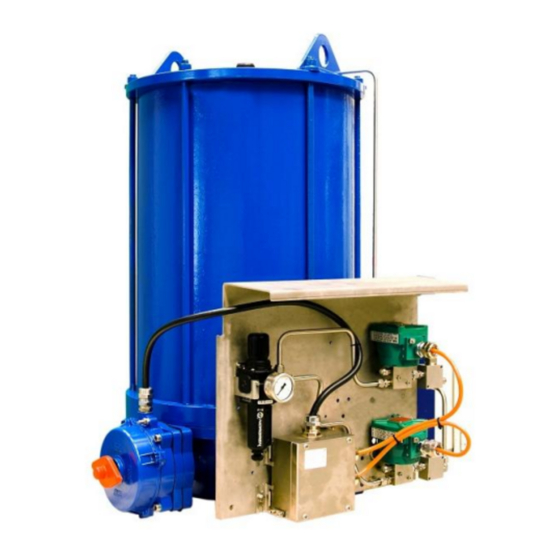
TPS Series
Single acting pneumatic actuator for quarter turn
applications
TURN PNEUMATIC – TPS Series
Compact pneumatic actuator – single acting
MAN 714
Use and maintenance manual
Drawn up according to CE Directives
- Translation of the original instructions -
Rev. 03 – Edition 07.2019
BIFFI ITALIA srl. - ITALIA – Strada BIFFI 165 - 29017 Fiorenzuola d'Arda (PC)
Phone +39 0523 94 44 11 – Fax +39 0523 94 18 85
Advertisement
Table of Contents

Subscribe to Our Youtube Channel
Related Manuals for BIFFI TPS Series


Summary of Contents for BIFFI TPS Series
- Page 1 Drawn up according to CE Directives - Translation of the original instructions - Rev. 03 – Edition 07.2019 BIFFI ITALIA srl. - ITALIA – Strada BIFFI 165 - 29017 Fiorenzuola d’Arda (PC) Phone +39 0523 94 44 11 – Fax +39 0523 94 18 85...
- Page 3 DOCUMENT REVISION TABLE Rev. Date Description Prepared Checked Approved 07/2013 Document release Comelli Comelli Vigliano Supplement: ATEX safety 09/2013 Comelli Comelli Vigliano provisions TPS 0.A model added Comelli Comelli Vigliano Standard ISO 5211 interface (extract from document SCN Comelli Comelli Vigliano 08/2016 7976) updated...
-
Page 5: Table Of Contents
TPS 0.1 / 0.3 / 0.9 / 1.5 / 3 Actuators .......................... 2.12 2.11.3 TPS 6 Actuator ................................2.13 2.11.4 TPS 14 / 18 / 32 Actuators ............................2.14 2.12 Technical data ..............................2.15 2.12.1 General data ................................2.15 MAN 714 TPS Series – Use and maintenance manual – Rev. 03... - Page 6 Assembly ..................................5.3 5.4.2 Pneumatic connections ..............................5.6 5.4.3 Electrical connections (if foreseen) ..........................5.7 COMMISSIONING AND ADJUSTMENTS ............... 6.1 Inspections prior to commissioning ........................6.1 Calibrating the angular stroke ..........................6.2 MAN 714 TPS Series – Use and maintenance manual – Rev. 03...
- Page 7 Lubrication ................................9.20 SPARE PARTS ...................... 10.1 10.1 Pneumatic cylinder seals (material: NBR) ......................10.1 10.2 Pneumatic cylinder seals (Fluorosilicone material)....................10.2 TROUBLESHOOTING ................... 11.1 DISMANTLING AND DISPOSAL ................12.1 MAN 714 TPS Series – Use and maintenance manual – Rev. 03...
- Page 8 F 9.7 – Hand tool types for pneumatic cylinder dis/assembly ................... 9.8 F 9.8 – Threaded bores for piston – ring assembly extraction (item 8a) ................. 9.12 F 9.9 – Threaded plugs on end flange (item 2) ....................... 9.17 MAN 714 TPS Series – Use and maintenance manual – Rev. 03...
- Page 9 T 9.5 – Info useful for seal replacement on pneumatic cylinder of TPS series actuators ..........9.19 T 10.1 - List of seal kits for pneumatic cylinder of TPS series actuators – NBR material ..........10.1 T 10.2 – List of seal kits for pneumatic cylinder of TPS series actuators – Fluorosilicone material ........ 10.2 T 11.1 –...
- Page 10 Manual. BIFFI Italia srl shall not be held responsible for any mistake or inaccuracy contained herein, or for any damage whether accidental or arising from the use of this manual. BIFFI Italia srl is the owner of intellectual property rights with regard to the content hereof, which can be subject to subsequent modifications without prior notice.
- Page 11 Biffi Italia srl owns all intellectual property rights over the content of this manual. Any reproduction thereof, in whole or in part, is prohibited without the prior written permission of Biffi Italia srl. Biffi Italia srl reserves the right to make changes without notice with respect to the content of this document.
- Page 12 Each symbol (ISO 7000) is identified by its related image, code number and meaning. 0421 EXAMINE – CHECK 0717 CALL FOR MAINTENANCE 0981 DATA CARRIER MAN 714 TPS Series – Use and maintenance manual – Rev. 03...
-
Page 13: General Information
Phone +39 0523 94 45 23 - Fax +39 0523 94 18 85 e-mail: service@biffi.it INFORMATION: Any inquiry or request for assistance submitted to the After Sales Service must indicate the data featured on the rating plate of the machine. MAN 714 TPS Series – Use and maintenance manual – Rev. 03... -
Page 14: Spare Parts Ordering
Purchaser shall be charged with both civil and criminal liability in relation to any improper use whatsoever of the actuator. Any other use not specifically indicated must be considered IMPROPER. MAN 714 TPS Series – Use and maintenance manual – Rev. 03... -
Page 15: Misuses
2.12 - Technical data, the provisions listed below must also be observed: ATMOSPHERE AT RISK OF FIRE It is FORBIDDEN to use TPS series actuators in environments at risk of fire and not equipped with suitable systems for the prevention and extinguishing of fires. INFORMATION:... -
Page 16: General Safety Provisions
Limitation of liability Biffi Italia srl declines all liability arising from the misuse or not reasonably foreseeable use of the actuator, use of non-genuine spare parts and from any modification or tampering whatsoever. -
Page 17: Regulatory Reference Framework
BIFFI Italia srl actuators are designed, manufactured and controlled according to the Quality Control System in compliance with EN ISO 9001 international Standard. Biffi Italia srl actuators, subject matter of the present document, are designed, manufactured and tested in compliance with the requirements and provisions laid down in the Directives and Standards listed below:... -
Page 19: Technical Description
The Purchaser must make sure the plate is never removed from the actuator and the featured data are always clearly legible. It is forbidden to modify the information and the marks without previous written authorization by BIFFI Italia srl. MAN 714 TPS Series – Use and maintenance manual – Rev. 03... - Page 20 “ “ field – line left empty for any particular remarks regarding the order acknowledgement In the lower part: The mark and data regarding the actuator performance and application limits pursuant to Directive 94/9/EC (ATEX): II 2 GD c 135°C (T4) MAN 714 TPS Series – Use and maintenance manual – Rev. 03...
- Page 21 2D or 1D Dusts Zone 22 3D, 2D or 1D This indication refers to the performance levels resulting from qualification tests performed by competent authority or certification laboratory. MAN 714 TPS Series – Use and maintenance manual – Rev. 03...
-
Page 22: General Safety Provisions
The list below contains the general safety provisions that must be strictly observed: Uses different from or additional to those provided in this Use and Maintenance Manual are not permitted and BIFFI Italia srl will not be liable for any damages arising from non-intended uses. -
Page 23: Safety Provisions For Installation In Hazardous Areas
TPS series pneumatic actuators must be installed and serviced according to the installation and servicing regulations for places classified against the risk of explosion due to the presence of gases / dusts or for mines (for instance: EN 60079-14, EN 60079-17, or other national regulations/standards). -
Page 24: Actuator Applications
(ref.: Section 2.14). INFORMATION: Connection to the valve stem is done by means of a bush insert or a sleeve machined internally (by Biffi Italia srl or by the customer) to fit the geometry of the valve stem. ... - Page 25 INFORMATION: The cylinder is provided also with the interface for the pneumatic supply of the cylinder lower chamber, which is to be used ONLY for double acting applications. In TPS series models, this interface is plugged (threaded, weather-proof plug). ...
-
Page 26: Main Features
Table T 2.3, page 2.9 INFORMATION: Pursuant to Standard ISO 5211, (clockwise direction of rotation to close the valve), in TPS series actuators: the CL configuration (spring to close), where the valve is closed by the spring, is obtained by the right- hand travel of the helical spline. -
Page 27: Options And Configurations
1300 T 2.3 – Output torque curve type – cylinders - springs Biffi Italia srl reserves the right to make changes without notice with respect to the data. For updated information, please refer to Biffi Italia srl website, catalogues, etc. -
Page 28: Accessories
As already mentioned in Section 2.1, the present manual DOES NOT contain any instruction as regards the use or maintenance of any of the accessories installed on TPS series actuators, for which you are kindly requested to refer to the documentation relative to the order acknowledgement (of which this manual is an integral part). -
Page 29: Main Components And Materials
Please refer to the documentation relative to the order acknowledgement for further details about the specifications of all spare parts materials and of the relevant reference standard MAN 714 TPS Series – Use and maintenance manual – Rev. 03 2.11... -
Page 30: 2.11.2 Tps 0.1 / 0.3 / 0.9 / 1.5 / 3 Actuators
Please refer to the documentation relative to the order acknowledgement for further details about the specifications of all spare parts materials and of the relevant reference standard 2.12 MAN 714 TPS Series – Use and maintenance manual – Rev. 03... -
Page 31: 2.11.3 Tps 6 Actuator
Please refer to the documentation relative to the order acknowledgement for further details about the specifications of all spare parts materials and of the relevant reference standard MAN 714 TPS Series – Use and maintenance manual – Rev. 03 2.13... -
Page 32: 2.11.4 Tps 14 / 18 / 32 Actuators
Please refer to the documentation relative to the order acknowledgement for further details about the specifications of all spare parts materials and of the relevant reference standard 2.14 MAN 714 TPS Series – Use and maintenance manual – Rev. 03... -
Page 33: Technical Data
The actuator ID code (Section 2.10) DOES NOT feature the data specified hereafter (in that regard, please refer to the documentation relative to the order acknowledgement): seal configuration and materials for each temperature range. MAN 714 TPS Series – Use and maintenance manual – Rev. 03 2.15... -
Page 34: 2.12.2 Overall Dimensions, Weights And Estimated Centre Of Gravity Position
COMPACT PNEUMATIC ACTUATOR - TPS Series Chapter 2 – Technical description 2.12.2 Overall dimensions, weights and estimated centre of gravity position F 2.7 – TPS actuator dimensions 2.16 MAN 714 TPS Series – Use and maintenance manual – Rev. 03... -
Page 35: T 2.7 - Technical Data For Each Model
REMARK: Overall dimensions and weights are the same in both Fail to Close (CL) and Fail to Open (OP) configurations for each actuator model. T 2.7 – Technical data for each model Biffi Italia srl reserves the right to make changes without notice with respect to the data. For updated information, please refer to Biffi Italia srl website, catalogues, etc. INFORMATION: For the overall dimensions and the weight, please refer to the confirmation documentation. -
Page 36: Valve Coupling Interface (Top Mounting)
Chapter 2 – Technical description 2.13 Valve coupling interface (Top Mounting) TPS series actuators allow direct coupling to the valve (without having to use a stub). The standard options for valve coupling interfaces available for TPS series actuators are listed below: INFORMATION:... -
Page 37: T 2.8 - Types Of Valve Interfaces
COMPACT PNEUMATIC ACTUATOR - TPS Series Chapter 2 – Technical description In short, TPS series actuators can be provided with three different valve coupling interfaces, as shown in the table below: Custom ALGA/ALGAS Standard - ISO 5211 Custom ISO 5211... -
Page 38: F 2.8 - Standard Iso 5211 Interface
REMARK: The above data are valid for both Fail to Close (CL) and Fail to Open (OP) configurations for each actuator model. T 2.9 – Technical data for standard flanges compliant with ISO 5211 2.20 MAN 714 TPS Series – Use and maintenance manual – Rev. 03... -
Page 39: F 2.9 - Custom Iso 5211 Interface
REMARK: The above data are valid for both Fail to Close (CL) and Fail to Open (OP) configurations for each actuator model. T 2.10 – Technical data for custom flanges compliant with ISO 5211 MAN 714 TPS Series – Use and maintenance manual – Rev. 03 2.21... -
Page 40: F 2.10 - Alga/Algas Interchangeable Interface
REMARK: The above data are valid for both Fail to Close (CL) and Fail to Open (OP) configurations for each actuator model. T 2.11 – Technical data for custom flanges interchangeable with ALGA/ALGAS actuators 2.22 MAN 714 TPS Series – Use and maintenance manual – Rev. 03... -
Page 41: Connecting The Stem Valve
Documents SCN 7975, SCN 7976, SCN 7977 contain also geometrical data as regards the output drive interface (actuator rotary element). Since there are no standard geometrical data regarding the valve stem, Biffi Italia srl provides a bush insert or a sleeve, suitably machined, which allows a rigid connection between actuator and valve. -
Page 42: Pneumatic Interfaces (Tps 6)
Please refer to the documentation relative to the order acknowledgement (in particular to the pneumatic functional diagram) to check the connection modes available for the pneumatic interfaces. 2.24 MAN 714 TPS Series – Use and maintenance manual – Rev. 03... -
Page 43: Pneumatic Interfaces (Tps 14 / 18 / 32)
Please refer to the documentation relative to the order acknowledgement (in particular to the pneumatic functional diagram) to check the connection modes available for the pneumatic interfaces. MAN 714 TPS Series – Use and maintenance manual – Rev. 03 2.25... -
Page 44: T 2.12 - Pneumatic Interfaces And Air Consumption
COMPACT PNEUMATIC ACTUATOR - TPS Series Chapter 2 – Technical description The pneumatic interfaces fitted on each TPS series model are listed in the table below. Pneumatic interface 1 Pneumatic interface 2 Displacement Model (pursuant to standard NPT) (pursuant to standard NPT) (litres) TPS 0.A xxk 175... -
Page 45: Other Interfaces, Devices And Accessories
All TPS series actuators are provided with a threaded interface on the base (4) for the earth connection. F 2.15 – Lower view with example of over pressure valve positioning MAN 714 TPS Series – Use and maintenance manual – Rev. 03 2.27... -
Page 46: Minimum Requirements For Installing Control, Signalling And Diagnostic Devices On Board The Actuator
F 2.16 – Detail of connection and coupling interface of valve status indicator device INFORMATION: Any indicator device requested by the customer can be installed by means of a customizable coupling and flange (both provided by Biffi Italia srl), for which you can refer to the documentation relative to the order acknowledgement. 2.19... -
Page 47: Health And Safety Provisions
INFORMATION: Biffi Italia srl shall in no way be liable for any damages or accidents to persons or property resulting from failure to comply with: the contents of this Instruction Manual;... -
Page 48: Duties Of The Safety Officer
The instructions contained in this manual and in the enclosed documentation, as regards the required competence to carry out maintenance activities, must be closely observed at all times. MAN 714 TPS Series – Use and maintenance manual – Rev. 03... -
Page 49: Residual Risks
Ensure that the actuator is not exposed to heat sources or placed in excessively hot environments. MAN 714 TPS Series – Use and maintenance manual – Rev. 03... -
Page 50: Information On Personal Protective Equipment (P.p.e.)
The type of P.P.E. to be used is decided by the Safety Officer appointed by the Employer. Nonetheless, in the table below are listed some PPE that Biffi Italia srl suggests to have always available because their usage represents the minimum safety level that must be guaranteed to all personnel interacting with the actuator during any transport, installation, processing, maintenance and disposal stage. -
Page 51: Transport And Handling
For further information: Chapter 5 P.P.E. to be used for lifting and handling operations: Weights: Table T 2.7, page 2.17 MAN 714 TPS Series – Use and maintenance manual – Rev. 03... -
Page 52: Lifting The Actuator
The lugs / eyes fitted on the actuator are designed to lift only the actuator WITHOUT the valve. For a correct use of the lifting lugs / eyes, please refer to the adhesive plate shown in figure F 2.2 as well as here below. MAN 714 TPS Series – Use and maintenance manual – Rev. 03... -
Page 53: Codes Of Practice For Lifting Operations
Check each time the conditions of all equipment used and discard it if not in perfect working order. Do not knot or twist the ropes so as not to reduce the lifting capacity or produce torsional effects on the load being lifted. MAN 714 TPS Series – Use and maintenance manual – Rev. 03... -
Page 54: Actuator Handling
4.3.1 General handling provisions Biffi Italia srl has provided purpose designed hooking (lugs and eyes) and lifting points on the actuator ( figure F 4.1). For handling operations by means of overhead lifting equipment, a crane or similar means can be used. - Page 55 Prevent suspended loads from swaying excessively and traverse at low speed. Code of practice: Provide for a person to stay on the ground and assist the driver in case of insufficient visibility. MAN 714 TPS Series – Use and maintenance manual – Rev. 03...
-
Page 57: Receipt And Installation Of Actuator
Rest the actuator on a wooden surface, being careful not to damage the coupling surface with the valve. Coat the coupling surface with oil, grease or protective disk to preserve its characteristics. MAN 714 TPS Series – Use and maintenance manual – Rev. 03... -
Page 58: Customer Duties
If the actuator is installed indoors, the room must be provided with proper lighting system, so as to prevent any hazard conditions. Safe installation information: The lighting of the premises where the machine is installed must not create dark areas, strong, dazzling or stroboscopic effects. MAN 714 TPS Series – Use and maintenance manual – Rev. 03... -
Page 59: Assembly Procedures
Refer to the documentation relative to the order acknowledgement to ensure that installation is consistent with the plant. Refer to the documentation relative to the order acknowledgement to check consistency between actuator to valve interface and coupling elements. MAN 714 TPS Series – Use and maintenance manual – Rev. 03... - Page 60 Keys and tabs ii. Threaded dowel screws b. Coupling flanges of valve and actuator i. Dowel or locating pins, if required ii. Threaded fasteners (stud bolts, bolts and nuts) MAN 714 TPS Series – Use and maintenance manual – Rev. 03...
-
Page 61: T 5.1 - Tightening Torques (Applicable For Screws In Astm A320 L7 And Nuts In Astm A194 Gr.7 S3)
Refer to the documentation relative to the order acknowledgment to check the materials of the fasteners used to fix the actuator to the valve. If the fasteners are supplied by Biffi Italia srl, apply the torques indicated in table T 5.1. MAN 714 TPS Series – Use and maintenance manual – Rev. 03... -
Page 62: Pneumatic Connections
3) Shape and fasten the pipes in such a way as not to cause unusual stress at the mouthpiece or loosening of threaded connections. 4) Carry out the connections according to the provided functional diagram (ref.: Section 2.14). 5) Check for leaks from the pneumatic connections. MAN 714 TPS Series – Use and maintenance manual – Rev. 03... -
Page 63: Electrical Connections (If Foreseen)
To ensure proper wiring, refer to the wiring diagram specified in the order acknowledgement. Tighten the cable gland. Replace the plastic plugs at the conduit mouthpiece with weather proof metal plugs. MAN 714 TPS Series – Use and maintenance manual – Rev. 03... -
Page 65: Commissioning And Adjustments
It is absolutely FORBIDDEN to commission the actuator prior to having performed all the inspections described above and under obvious faulty or potentially hazardous conditions. MAN 714 TPS Series – Use and maintenance manual – Rev. 02... -
Page 66: Calibrating The Angular Stroke
The angular stroke (0° – 90°) of the quarter turn valve might need to be adjusted owing to misalignment between valve stem and actuator. In all TPS series models, the rotation angle of the output drive can be adjusted by changing by ± 5° its end positions (OPEN – CLOSED) within the limit values of -5°; +95°, by means of two mechanically adjustable end stoppers. -
Page 67: F 6.2 - Stopper Operation
+85° ; +95°, so that the output drive can be aligned with the valve stem when in OPEN status. INFORMATION: For every model of the TPS series, the position of the stoppers, used to adjust the angular stroke of the output drive, is the same for both OP and CL configurations. -
Page 68: F 6.3 - Stopper Components
This prevents polluting agents from getting inside the stopper guard. By using a type A wrench, it can be removed so as to reach and move the stopper. 4. Seal This prevents polluting agents from getting inside the stopper guard. MAN 714 TPS Series – Use and maintenance manual – Rev. 02... -
Page 69: T 6.1 - Wrench Sizes For Stopper Adjustment
REMARK: The above data are valid for both Fail to Close (CL) and Fail to Open (OP) configurations for each actuator model. T 6.1 – Wrench sizes for stopper adjustment MAN 714 TPS Series – Use and maintenance manual – Rev. 02... -
Page 71: Biffi Limit Switch Box (If Fitted)
Chapter 7 – Biffi limit switch box BIFFI LIMIT SWITCH BOX (IF FITTED) Biffi limit switch box, in its various configurations, is one of the devices that can be installed on TPS series actuator to indicate the position of the actuator. -
Page 72: Limit Switch Calibration Procedure
(“Open” or “Closed”). 10) Tighten the screws on the cover. 11) Restore the power supply. F 7.2 – Cam calibration MAN 714 TPS Series – Use and maintenance manual – Rev. 02... -
Page 73: Indicator Reset Procedure
F 7.3 – Status indicator and roll pin 1. Status indicator 2. Roll pin Slowly turn the indicator to the correct position. Put the roll pin back in place. MAN 714 TPS Series – Use and maintenance manual – Rev. 02... -
Page 75: Routine Maintenance
Chapter 8 – Routine maintenance ROUTINE MAINTENANCE TPS series actuators are designed to run without requiring maintenance for long periods under hard operating and environmental conditions (ref.: Section 2.12) as well as in unmanned areas. Despite that, owing to the great number of different conditions in terms of environment, operation and installation, it is however recommended, for this type of product, to perform routine maintenance interventions on a biannual basis, as described below. -
Page 76: Monitoring And Visual Inspection Activities
(if the actuator model is provided with such function) Perform the periodic maintenance interventions specified in Section 8.2 Ref.: Section 8.2 T 8.2 – Checks for SIL certification MAN 714 TPS Series – Use and maintenance manual – Rev. 02... -
Page 77: Supplementary Maintenance
Italia srl recommends that the supplementary maintenance interventions described in the present manual be executed: in a preventative and planned manner, every time a stoppage of the plant, where a TPS series actuator is installed, is scheduled for maintenance purposes. -
Page 78: General Information About Supplementary Maintenance
(even in those cases where installation conditions can cause components to fall if not adequately handled). MAN 714 TPS Series – Use and maintenance manual – Rev. 03... - Page 79 In view of the complexity and residual risks mentioned in the present manual, supplementary maintenance interventions can be performed exclusively by personnel provided by Biffi Italia srl or qualified on a training course provided by Biffi Italia srl. Please contact Biffi Italia srl (ref.: Section 1.1) for further information.
-
Page 80: Technical Guidelines For Replacing The Pneumatic Cylinder Seals
Technical guidelines for replacing the pneumatic cylinder seals 9.2.1 General description Figure F 9.1 shows a 2D section of a TPS series generic actuator model, with a detailed view of all the pneumatic cylinder seals, identified by alphanumeric indexing. Detail A... -
Page 81: F 9.2 - Pneumatic Cylinder Components
COMPACT PNEUMATIC ACTUATOR - TPS Series Chapter 9 – Supplementary maintenance The codes for the pneumatic cylinder seals, for all TPS series actuator models, are listed in tables T 10.1 and T 10.2. The figure below shows a detailed 2D view of the main components, identified by numeric indexing, that have to be disassembled when replacing the pneumatic cylinder seals. -
Page 82: F 9.3 - Pneumatic Cylinder Exploded View
The plug (item 8b) has to be disassembled in order to replace seals E and F (ref.: figure F 9.1, table T 9.1). In this way, the operator can gain access to the components of the retaining system of the thrust flange (item 8c). MAN 714 TPS Series – Use and maintenance manual – Rev. 03... -
Page 83: F 9.4 - Retaining System Of The Thrust Flange
Figure F 9.5 shows, more in detail, how the safety ring (item 8d) works and in what way it keeps the retaining half rings (item 8e) in place, preventing them from slipping out of their housing. F 9.5 – Retaining system of the thrust flange – section view MAN 714 TPS Series – Use and maintenance manual – Rev. 03... -
Page 84: F 9.6 - Retaining System Of The Thrust Flange - Detail Of Half Rings Without Safety Ring
Key (Type A): screws (items V1, V2 and V3) Wrench (Type B): nuts (item 1) Allen Wrench (Type A) (Type B) F 9.7 – Hand tool types for pneumatic cylinder dis/assembly MAN 714 TPS Series – Use and maintenance manual – Rev. 03... -
Page 85: Partial Or Total Seal Replacement
The lower chamber, in single acting applications, houses the spring and is never pressurized; consequently, the head flange seal (ref.: Item F, figure F 9.1), besides being a static seal (meaning it is not subject to wear over time), also prevents polluting agents from getting inside the actuator (in TPS Series actuators). -
Page 86: Disassembling The Pneumatic Cylinder
Pneumatic cylinder disassembly procedure for seal replacement move the fitting screwed to the pneumatic interface 1 (ref.: figures F 2.11, F 2.12, F 2.13) and used to supply the cylinder upper chamber. 9.10 MAN 714 TPS Series – Use and maintenance manual – Rev. 03... - Page 87 Biffi Italia srl can provide the specific fixture that allows the cylinder to stay locked, by keeping it in place, during disassembly and seal replacement (ref.: section 9.3) Remove the tie rod nuts (item 1).
-
Page 88: F 9.8 - Threaded Bores For Piston - Ring Assembly Extraction (Item 8A)
The removal of the screws (item V3, F 9.2) affects the functional performance of the retaining system of the thrust flange (item 8c, F 9.2), which is compressed by means of the spring. 9.12 MAN 714 TPS Series – Use and maintenance manual – Rev. 03... - Page 89 (according to the actuator dimensions). MAN 714 TPS Series – Use and maintenance manual – Rev. 03 9.13...
-
Page 90: Replacing The Seals
Grease and lubricate the seals in their housings and the sliding ring, so as to keep them in place during assembly. INFORMATION: As regards seal lubrication, Biffi Italia srl recommends this grease : AGIP-ENI LCX 2/32 for NBR/Viton/Neoprene seals; Aeroshell Grease 7 for Fluoro-silicon seals INFORMATION: In the case where it was decided to perform a partial replacement of the pneumatic cylinder seals, the ... - Page 91 As regards the type of hand tools required to assemble the cylinder, refer to figure F 9.7. NO specific tightening torque is prescribed for the screws (items V1 and V2); nonetheless, the screws must be tightened properly. Use a sealant (Loctite 510 or equivalent, recommended by Biffi Italia srl) to take preventive measures.
- Page 92 (item 8b, F 9.2). Ensure that the seal (item A, detail A, figure F 9.1 - table T 9.1) of end flange (item 2, F 9.2). 9.16 MAN 714 TPS Series – Use and maintenance manual – Rev. 03...
-
Page 93: F 9.9 - Threaded Plugs On End Flange (Item 2)
5, F 9.2) and be careful not to damage the seal (item A, ref.: detail A, figure F 9.1- table T 9.1 – Pneumatic cylinder seals for TPS series actuators). The end flange should rest against the cylinder. Tighten the nuts (item 1) on the tie rods (item 3) (ref.: figure F 9.2 and figure F 9.3). - Page 94 Owing to the fact that TPS series actuators can be equipped with various different types of pneumatic cylinders (ref.: table T 2.3), there are various types of fixtures available, to suit the cylinder in use.
-
Page 95: T 9.5 - Info Useful For Seal Replacement On Pneumatic Cylinder Of Tps Series Actuators
REMARK: with reference to the ID code of the actuator model (section 2.10), the data featured in this table depend neither on the type of kinematic mechanism (xx = RP/SY) nor on the type of spring (k = 1/2/3) T 9.5 – Info useful for seal replacement on pneumatic cylinder of TPS series actuators MAN 714 TPS Series – Use and maintenance manual – Rev -02... - Page 96 In case the cylinder motions are extremely frequent, lubrication of the sliding and contact surfaces should be restored with grease. The type of grease used and recommended by BIFFI Italia srl for lubrication purposes at normal temperature, is described below:...
-
Page 97: T 10.1 - List Of Seal Kits For Pneumatic Cylinder Of Tps Series Actuators - Nbr Material
REMARK: The above data are valid for both Fail to Close (CL) and Fail to Open (OP) configurations for each actuator model. T 10.1 - List of seal kits for pneumatic cylinder of TPS series actuators – NBR material MAN 714 TPS Series – Use and maintenance manual – Rev -03... -
Page 98: T 10.2 - List Of Seal Kits For Pneumatic Cylinder Of Tps Series Actuators - Fluorosilicone Material
REMARK: The above data are valid for both Fail to Close (CL) and Fail to Open (OP) configurations for each actuator model. T 10.2 – List of seal kits for pneumatic cylinder of TPS series actuators – Fluorosilicone material 10.2... -
Page 99: T 11.1 - Troubleshooting
TPS actuator. This list has been drawn up on the basis of data processed by Biffi Italia srl after examining the failures or shortcomings occurred over the years on actuators already installed. Therefore, this list should not be considered complete and exhaustive, but rather a collection of the most frequent cases. - Page 101 Dismantle the actuator and group the components according to the type of material (e.g. metal, plastic, fluids, etc.) and dispose of them as separately collected fractions, in compliance with the Laws and Regulations in force. MAN 714 TPS Series – Use and maintenance manual – Rev -03 12.1...
Need help?
Do you have a question about the TPS Series and is the answer not in the manual?
Questions and answers