Table of Contents
Advertisement
Quick Links
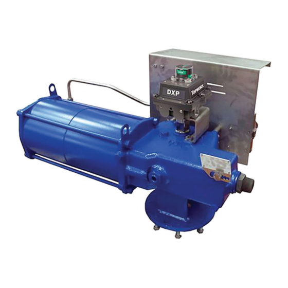
Biffi RPS
Spring-Return Pneumatic Actuator
Copyright © Biffi. The information in this document is subject to change without notice. Updated data sheets can be obtained from our website www.biffi.it or from your nearest Biffi Center:
Biffi Italia s.r.l. - Strada Biffi 165, 29017 Fiorenzuola d'Arda (PC) – Italy PH: +39 0523 944 411 – biffi_italia@biffi.it
Installation, Operation and Maintenance Manual
MAN 573 Rev. 8
July 2020
Advertisement
Table of Contents

Subscribe to Our Youtube Channel
Related Manuals for BIFFI RPS Series


Summary of Contents for BIFFI RPS Series
- Page 1 Spring-Return Pneumatic Actuator Copyright © Biffi. The information in this document is subject to change without notice. Updated data sheets can be obtained from our website www.biffi.it or from your nearest Biffi Center: Biffi Italia s.r.l. - Strada Biffi 165, 29017 Fiorenzuola d'Arda (PC) – Italy PH: +39 0523 944 411 – biffi_italia@biffi.it...
- Page 2 Revision Details Installation, Operation and Maintenance Manual July 2020 MAN 573 Rev. 8 Revision Details Rev. Date Description Prepared Checked Approved July 2020 General update (Migration to new template) Added Sectional drawings for November 2019 Ermanni Orefici Vigliano MSJ-MHW and DMHW March 2018 Updated Data-plate Ermanni...
-
Page 3: Table Of Contents
Installation, Operation and Maintenance Manual Table of Contents MAN 573 Rev. 8 July 2020 Table of Contents Section 1: General Warnings Generalities ....................1 1.1.1 Applicable Regulation ................ 1 1.1.2 Terms and Conditions ................. 1 Identification Plate ..................2 Introducing the Actuator ................2 Data Sheet .................... - Page 4 Table of Contents Installation, Operation and Maintenance Manual July 2020 MAN 573 Rev. 8 Section 6: Troubleshooting Failure or Breakdown Research ..............28 Section 7: Layouts Spare Parts Order ..................29 Parts List for Maintenance and Replacing Procedure ........30 Section 8: Date Report for Maintenance Operations Date Report for Maintenance Operations ..............
-
Page 5: Section 1: General Warnings
Biffi Italia s.r.l. pays the highest attention to collecting and verifying the documentation contained in this user manual. However Biffi Italia s.r.l. is not liable for any mistakes contained in this manual, for damage or accidents due to the use of the latter. The information contained is of exclusive reserved ownership of Biffi Italia s.r.l. -
Page 6: Identification Plate
MAN 573 Rev. 8 Identification Plate WARNING It is forbidden to modify the information and the marks without previous written authorization by Biffi Italia s.r.l. The plate fastened on the actuator contains the following information (see Figure 1). Figure 1 Data Plate... - Page 7 Installation, Operation and Maintenance Manual Section 1: General Warnings MAN 573 Rev. 8 July 2020 Figure 2 View from X View from Y ØE ØF ØC ØC №4 threaded №4 threaded holes holes ØH Threaded hole ØN Joint detail Threaded hole ØN ØM Both the actuator flanges can be used for valve coupling or the mounting of ancillary equipment (positioner, limit switch box, etc.).
- Page 8 Section 1: General Warnings Installation, Operation and Maintenance Manual July 2020 MAN 573 Rev. 8 Figure 3 ±0.2 Front side ØE №4 threaded holes Top view ±0.2 Back side ØE №4 threaded holes (optional) Table 2. Dimensions in mm Model ØE 12.5 The expected lifetime of actuator is approximately 25 years.
-
Page 9: Data Sheet
Installation, Operation and Maintenance Manual Section 1: General Warnings MAN 573 Rev. 8 July 2020 Data Sheet Supply fluid: Air, Nitrogen or sweet gas Operating temperature: Standard: from –30 °C to +100 °C Optional: from –60 °C to +140 °C Design pressure: 12 bar maximum Supply pressure:... -
Page 10: Section 2: Installation
Section 2: Installation Installation, Operation and Maintenance Manual July 2020 MAN 573 Rev. 8 Section 2: Installation Checks upon Actuator Receipt • Check that the model, the serial number of the actuator and the technical data reported on the identification plate correspond with those of order confirmation (Section 1.2). •... - Page 11 The actuator can also be lifted to assemble directly onto the valve with stem with horizontal axis. To make easier this operation, Biffi suggest to move the lifting eyelet from its standard position, and place it in this suggested position:...
-
Page 12: Storage
Section 2: Installation Installation, Operation and Maintenance Manual July 2020 MAN 573 Rev. 8 Figure 6 Actuator Models: RPS Stabilizing eyelet (DON'T USE FOR LIFT) Stabilizing eyelet (DON'T USE FOR LIFT) Lifting eyelets Lifting eyelet Lifting eyelet Rack and Pinion When it's necessary to lift the actuator, in order to stabilize the RPS actuator during the transport in horizontal position, it's recommendable to fix the actuator by the "stabilizing eyelets"... -
Page 13: Actuator Assembly On The Valve
(cylinder axis parallel or perpendicular to the pipeline axis). NOTICE To fix the actuator to the valve flange must be used the stud bolts and nuts supplied by Biffi. In case the actuator is supplied without stud bolts and nuts, the following materials must be used as a minimum: •... - Page 14 Section 2: Installation Installation, Operation and Maintenance Manual July 2020 MAN 573 Rev. 8 Figure 8 "RP" Pneumatic Actuators Coupling Dimensions - Overall Dimensions View from X View from Y ØE ØF ØC ØC №4 threaded №4 threaded holes holes ØH Threaded hole ØN Joint detail...
-
Page 15: Assembly Procedure
Installation, Operation and Maintenance Manual Section 2: Installation MAN 573 Rev. 8 July 2020 2.4.2 Assembly procedure NOTICE Failure to comply with the following procedures may impair product warranty. WARNING Installation, commissioning and maintenance and repair works should be carried out by qualified staff. A non-conforming assembly could be the source of serious accidents. -
Page 16: Pneumatic Connections
Section 2: Installation Installation, Operation and Maintenance Manual July 2020 MAN 573 Rev. 8 Pneumatic Connections Connect the actuator to the pneumatic feed line with fittings and pipes in accordance to the plant specifications. They must be sized correctly in order to guarantee the necessary air flow for the operation of the actuator, with pressure drops not exceeding the maximum allowable value. -
Page 17: Commissioning
Any calibration relative to functional aspects of the actuator are preset at the factory, except the angular stroke setting because for this setting operation, the actuator must be placed on to the valve (see Section 3.4). Before any modifications please contact Biffi Italia s.r.l. Upon actuator commissioning please carry out the following checks: •... -
Page 18: Section 3: Operation And Use
Section 3: Operation and Use Installation, Operation and Maintenance Manual July 2020 MAN 573 Rev. 8 Section 3: Operation and Use Operation Description The air pressurizes the cylinder chamber and this pressure starts the linear motion of the piston and the consequent rotation motion of the rack and pinion mechanism, to which the valve stem is coupled, in one direction. - Page 19 Installation, Operation and Maintenance Manual Section 3: Operation and Use MAN 573 Rev. 8 July 2020 Figure 11 ON-OFF Service: Three way control valve Manual control Pressurized air Solenoid control Atmospheric pressure air Pneumatic pilot control The Figure shows the simplest ON-OFF control. The control valve (2) has two positions. In one position, the gas supply pressure is connected to the cylinder chamber, and the actuator performs the “pneumatic”...
-
Page 20: Residual Risks
Operations The operations are carried out sending the proper signal through the control system in compliance with Customer specifications. Please refer to applicable “operating diagram” and to Biffi technical documentation supplied. Operation and Use... -
Page 21: Calibration Of The Angular Stroke
Installation, Operation and Maintenance Manual Section 3: Operation and Use MAN 573 Rev. 8 July 2020 Calibration of the angular stroke WARNING It is important that the mechanical stops of the actuator (and not those of the valve) stop the angular stroke at both extreme valve position (fully open and fully closed), except when this is required by the valve operation (e.g. - Page 22 Section 3: Operation and Use Installation, Operation and Maintenance Manual July 2020 MAN 573 Rev. 8 Table 6. Without jackscrew manual override Actuator Model WRENCH C1 (mm) Wrench C2 (mm) RP 14/15 RP 30 RP 60 RP 120 Figure 14 Table 7.
-
Page 23: Calibration Of Micro-Switches (If Foreseen)
Adjust the relative cams properly. Calibration of the Operation Time The calibration of the operation time is made by Biffi Italia s.r.l. according to customer requirements and to technical data sheet included in technical documentation. If necessary, it’s possible to modify or reset the operating time through the flow regulator valve placed on inlet of pneumatic supply (Figure 16). -
Page 24: Section 4: Operational Tests And Inspections
Section 4: Operational Tests and Inspections Installation, Operation and Maintenance Manual July 2020 MAN 573 Rev. 8 Section 4: Operational Tests and Inspections NOTICE To ensure the guaranteed SIL grade, according to IEC 61508, the functionality of actuator must be checked with regular intervals of time, as described in the Safety Manual. -
Page 25: Section 5: Maintenance
Section 5: Maintenance Installation, Operation and Maintenance Manual MAN 573 Rev. 8 July 2020 Section 5: Maintenance NOTICE Before executing any maintenance operation, it is necessary to close the pneumatic feed line and discharge pressure from the cylinder of the actuator and from the control unit (if foreseen) to ensure the safety of maintenance staff. -
Page 26: Extraordinary Maintenance
Section 5: Maintenance Installation, Operation and Maintenance Manual July 2020 MAN 573 Rev. 8 Extraordinary Maintenance If there are leaks in the pneumatic cylinder or a malfunction in the mechanical components, or in case of scheduled preventive maintenance, the actuator must be disassembled, and seals must be replaced with reference to the follow general sectional drawing and adopting the following procedures. - Page 27 Section 5: Maintenance Installation, Operation and Maintenance Manual MAN 573 Rev. 8 July 2020 Seals replacement Prior to reassemble check that the actuator components are in good conditions and clean. Lubricate all the surfaces of the parts, which move in contact with other components, by recommended grease (AGIP-ENI LCX 2/32 if seals are in NBR/Viton or Neoprene rubber, or with Aeroshell Grease 7 if the seals are in Fluorosilicon rubber).
- Page 28 Section 5: Maintenance Installation, Operation and Maintenance Manual July 2020 MAN 573 Rev. 8 Replacement of mechanism seals (see Sectional drawing) To replace the O-Rings of the shaft (6) proceed as follows: Remove the retainer ring (21). Disassemble the shoulder washer (8). Remove the existing O-Ring (23) from its groove. Clean the groove and the shaft carefully and lubricate it with protective grease film.
- Page 29 Section 5: Maintenance Installation, Operation and Maintenance Manual MAN 573 Rev. 8 July 2020 Figure 17 RPS Spring-Return Pneumatic Actuator Table 8. Parts List Item Description Housing Pinion Piston End flange Rack Shaft Cylinder gasket Shoulder washer Spring retainer disk Rack spacer rod Cylinder tube Tie rod...
-
Page 30: Lubrication Of Mechanism
Section 5: Maintenance Installation, Operation and Maintenance Manual July 2020 MAN 573 Rev. 8 Lubrication of Mechanism For normal duty the rack and pinion mechanism of the actuator is lubricated "for life". In case of high load and high frequency of operation, it may be necessary to periodically restore lubrication: it is advisable to apply a generous coating of grease on the contact surfaces of moving parts, especially on the surface of the rack in contact with the thrust bearing sliding block and on the teeth of the rack and pinion. -
Page 31: Dismantling And Demolition
Section 5: Maintenance Installation, Operation and Maintenance Manual MAN 573 Rev. 8 July 2020 The following grease is used by Biffi for standard working temperature and suggested for relubrication: Table 9. AGIP MU/EP/2 AEROSHELL GREASE 7 or equivalent To be used in standard To be used in low (-30 °C / +85 °C) -
Page 32: Section 6: Troubleshooting
Clean or replace the cartridge Blocked valve Repair or replace Actuator does not work Failure of the spring Call Biffi Italia s.r.l. Customer Service Failure of the control system Call Biffi Italia s.r.l. Customer Service Low supply pressure Restore (Section 1.4) Low supply pressure Restore (Section 1.4) -
Page 33: Section 7: Layouts
Section 7: Layouts Spare Parts Order For spare parts order to the relevant Biffi office please make reference to Biffi order confirmation concerning all the supply, and serial number of the actuator (Section 1.2) for any specific spare part for a specific actuator model. -
Page 34: Parts List For Maintenance And Replacing Procedure
Section 7: Layouts Installation, Operation and Maintenance Manual July 2020 MAN 573 Rev. 8 Parts List for Maintenance and Replacing Procedure Figure 19 Rack and pinion mechanism RPS S2–*1 Single-Acting Pneumatic Actuator Table 11. Parts List Item Qty. Description Material Housing Nodular cast iron Pinion... - Page 35 Installation, Operation and Maintenance Manual Section 7: Layouts MAN 573 Rev. 8 July 2020 Figure 20 RPS S2 –*2 Single-Acting Pneumatic Actuator Table 12. Parts List Item Qty. Description Material Housing Nodular cast iron Pinion Nodular cast iron Piston Carbon steel End flange Low temperature carbon steel Rack...
- Page 36 Section 7: Layouts Installation, Operation and Maintenance Manual July 2020 MAN 573 Rev. 8 Figure 21 RPS 2.4 / RPS 3.1 Single-Acting Pneumatic Actuator Table 13. Parts List Item Qty. Description Material Housing Nodular cast iron Pinion Nodular cast iron Piston Carbon steel End flange...
- Page 37 Installation, Operation and Maintenance Manual Section 7: Layouts MAN 573 Rev. 8 July 2020 Figure 22 RPS MSJ / MHW Single-Acting Pneumatic Actuator 17 34 35 Table 14. Parts List Item Qty. Description Material Housing Nodular cast iron Pinion Nodular cast iron Piston Carbon steel End flange...
- Page 38 Section 7: Layouts Installation, Operation and Maintenance Manual July 2020 MAN 573 Rev. 8 Figure 23 Declutchable Padlockable Manual Override DMHW (Optional) Table 15. Parts List Item Qty. Description Material External body Carbon steel Internal body Carbon steel Scraper ring NBR Rubber Flap Carbon steel...
-
Page 39: Section 8: Date Report For Maintenance Operations
Installation, Operation and Maintenance Manual Section 8: Date Report for Maintenance Operations MAN 573 Rev. 8 July 2020 Section 8: Date Report for Maintenance Operations Last maintenance operation date: (in factory, on delivery ): ..exec. by: ...... exec. by: ..... - Page 40 VCIOM-03749-EN ©2020 Biffi. All rights reserved. Biffi Italia s.r.l. Strada Biffi 165 The contents of this publication are presented for information purposes only, 29017 Fiorenzuola d’Arda (PC) and while every effort has been made to ensure their accuracy, they are not...
Need help?
Do you have a question about the RPS Series and is the answer not in the manual?
Questions and answers