Table of Contents
Advertisement
Quick Links
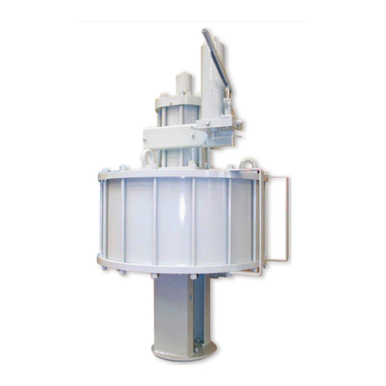
Biffi PLA
Double-Acting Pneumatic Linear Actuator
Copyright © Biffi. The information in this document is subject to change without notice. Updated data sheets can be obtained from our website www.biffi.it or from your nearest Biffi Center:
Biffi Italia s.r.l. - Strada Biffi 165, 29017 Fiorenzuola d'Arda (PC) – Italy PH: +39 0523 944 411 – biffi_italia@biffi.it
Installation, Operation and Maintenance Manual
MAN 619 Rev. 4
June 2020
Advertisement
Table of Contents

Subscribe to Our Youtube Channel
Related Manuals for BIFFI PLA


Summary of Contents for BIFFI PLA
- Page 1 Double-Acting Pneumatic Linear Actuator Copyright © Biffi. The information in this document is subject to change without notice. Updated data sheets can be obtained from our website www.biffi.it or from your nearest Biffi Center: Biffi Italia s.r.l. - Strada Biffi 165, 29017 Fiorenzuola d'Arda (PC) – Italy PH: +39 0523 944 411 – biffi_italia@biffi.it...
- Page 2 Revision Details Installation, Operation and Maintenance Manual June 2020 MAN 619 Rev. 4 Revision Details Rev. Date Description Prepared Checked Approved June 2020 General update (Migration to new template) May 2018 Updated Data-plate Ermanni Orefici Vigliano April 2016 Updated applicable regulation (Section 1.1.1) Ermanni Orefici Vigliano...
-
Page 3: Table Of Contents
3.3.4 Emergency Manual Operation by MHP ..........17 Calibration of The Linear Stroke ..............17 Calibration of Micro-Switches (for Biffi limit switch box*) ......20 Calibration of the Operation Time ............22 Section 4: Operational Tests and Inspections Operational Tests and Inspections ..............24... - Page 4 Table of Contents Installation, Operation and Maintenance Manual June 2020 MAN 619 Rev. 4 Section 5: Maintenance Periodic Maintenance ................25 5.1.1 Check and Restore Oil Level in the Gas-Hydraulic Tanks ....26 5.1.2 Gas Supply Dehydrating Filter Maintenance (if foreseen) ....27 5.1.3 Lubrication of Actuator ..............
-
Page 5: Section 1: General Warnings
Biffi Italia s.r.l. pays the highest attention to collecting and verifying the documentation contained in this user manual. However Biffi Italia s.r.l. is not liable for any mistakes contained in this manual, for damage or accidents due to the use of the latter. -
Page 6: Terms And Conditions
1.1.2 Terms and Conditions Biffi Italia s.r.l. guarantees that all the items produced are free of defects in workmanship and manufacturing materials and meet relevant current specifications, provided they are installed, used and serviced according to the instructions contained in the present manual. -
Page 7: Introducing The Actuator
MAN 619 Rev. 4 June 2020 Introducing the Actuator PLA Double-Acting Pneumatic Low-Pressure Linear Actuators, are suitable for the operation of linear valves (wedge gate valves, through conduit gate valves) for ON-OFF and modulating heavy-duty service. The actuator is made up of a pneumatic cylinder and a mounting pedestal complete with a joint for the coupling to the valve stem of actuator output stem. -
Page 8: Data Sheet
Section 1: General Warnings Installation, Operation and Maintenance Manual June 2020 MAN 619 Rev. 4 250k Manual override Stroke (mm) Cylider diameter (mm) Max. allowable thrust (N) Double-Acting actuator Data sheet Supply fluid Air, Nitrogen or sweet gas Operating temperature Standard: from –30 °C to +100 °C Optional: from –60 °C to +140 °C Supply pressure... -
Page 9: Section 2: Installation
The actuator should be handled with appropriate lifting means. The weight of the actuator is reported on the delivery bill. For a correct lifting procedure, please refer to following Figures. Figure 3 Lifting Points for PLA Actuators 1 = Lifting points (obligatory) Installation... -
Page 10: Storage
Section 2: Installation Installation, Operation and Maintenance Manual June 2020 MAN 619 Rev. 4 Figure 4 Positioning by chains and by slings Point of support Don’t lay the actuator on tie-rods of cylinder Don’t lay the actuator on accessories (manual handpump, manual jackscrew, pneumatic control group etc.) Storage If the actuator needs storage, before installation follow these steps: •... -
Page 11: Actuator Assembly On The Valve
Installation, Operation and Maintenance Manual Section 2: Installation MAN 619 Rev. 4 June 2020 Actuator Assembly on the Valve 2.4.1 Types of Assembly The adapter pedestal in fabricated carbon steel is specifically designed for adaptation to any type of valve with provision for local indicator, limit switches and other accessories (on request). - Page 12 Section 2: Installation Installation, Operation and Maintenance Manual June 2020 MAN 619 Rev. 4 To assemble the actuator onto the valve by bracket with threaded joint proceed as follows: Figure 5 Pedestal with threaded coupling joint Table 1. Parts list Item Description Stud bolt...
- Page 13 Installation, Operation and Maintenance Manual Section 2: Installation MAN 619 Rev. 4 June 2020 Check that the coupling dimensions of the valve flange and stem, or of the relevant extension, meet the actuator coupling dimensions (valve stem and flange). Lubricate the valve stem with grease in order to make the assembly easier. Connect a sling to the support point of the actuator and lift it.
- Page 14 Section 2: Installation Installation, Operation and Maintenance Manual June 2020 MAN 619 Rev. 4 To assemble the actuator onto the valve by bracket with shell joint, perform the following operations: Figure 6 Pedestal with shell coupling joint Table 2. Parts list Item Description Stud bolt...
- Page 15 Installation, Operation and Maintenance Manual Section 2: Installation MAN 619 Rev. 4 June 2020 Check that the coupling dimensions of the valve flange and stem, or of the relevant extension, meet the actuator coupling dimensions (valve stem and flange). Lubricate the valve stem with grease in order to make the assembly easier. To make easier the assembly, the valve stem has to be in perfect vertical position.
-
Page 16: Pneumatic Connections
Section 2: Installation Installation, Operation and Maintenance Manual June 2020 MAN 619 Rev. 4 Pneumatic Connections WARNING Check that the values of pneumatic supply available are compatible with those reported on the identification plate of the actuator. NOTICE The connections should be made by qualified staff. Use pipes and connections appropriate as for type, material and dimensions. -
Page 17: Commissioning
Installation, Operation and Maintenance Manual Section 2: Installation MAN 619 Rev. 4 June 2020 Commissioning WARNING Installation, commissioning and maintenance and repair works should be made by qualified staff. Upon actuator commissioning please carry out the following checks: • Check that paint hasn't been damaged during transport, if necessary repair the damages to paint coat. -
Page 18: Section 3: Operation And Use
Section 3: Operation and Use Installation, Operation and Maintenance Manual June 2020 MAN 619 Rev. 4 Section 3: Operation and Use Operation Description The supply gas pressurizes the pneumatic-cylinder chamber relevant to the operation to carry out (opening or closing) (see following pages). This pressure starts the linear motion of the piston and the consequent motion of the valve stem that is coupled. -
Page 19: Residual Risks
Installation, Operation and Maintenance Manual Section 3: Operation and Use MAN 619 Rev. 4 June 2020 Figure 9 Double-Acting function with jackscrew manual override type MHP Residual Risks WARNING It is recommended to pipe exhaust gas. The actuator has parts under pressure. Use the due caution. -
Page 20: Electric Remote Control To Open And To Close
Section 3: Operation and Use Installation, Operation and Maintenance Manual June 2020 MAN 619 Rev. 4 Figure 10 PLAS MHP without control system Pressurize the pneumatic-cylinder chamber, this pressure starts the linear motion of the piston and the consequent motion of the valve stem that is coupled. The valve is actuated in opening and in closing position by the actuator pneumatic cylinder in one direction and by the spring unit in the other direction. -
Page 21: Emergency Manual Operation By Mhp
Installation, Operation and Maintenance Manual Section 3: Operation and Use MAN 619 Rev. 4 June 2020 3.3.4 Emergency Manual Operation by MHP (when sufficient line pressure is not available) • Select by the valve 5-D the opening or closing operation. •... - Page 22 June 2020 MAN 619 Rev. 4 For the adjustment in PLA with hydraulic manual override the mechanical stop is placed on the end flange of hydraulic cylinder, follow these steps (Figure 12): Remove with the specific wrench (c1) the plug (t).
- Page 23 Installation, Operation and Maintenance Manual Section 3: Operation and Use MAN 619 Rev. 4 June 2020 For the adjustment of the mechanical stop screwed on the end flange of manual override (see also Section 7.2, Table 14: sectional drawing for manual jackscrew MSJ) proceed as follows: Loosen the lock nut (item 2).
-
Page 24: Calibration Of Micro-Switches (For Biffi Limit Switch Box*)
Section 3: Operation and Use Installation, Operation and Maintenance Manual June 2020 MAN 619 Rev. 4 Calibration of Micro-Switches (for Biffi limit switch box*) WARNING *If different micro-switches assembly or limit switch box is supplied, please refer to the specific documentation. NOTICE Operate only the micro-switch corresponding to the direction of operation being carried out, as clearly reported on the micro-switch. - Page 25 Installation, Operation and Maintenance Manual Section 3: Operation and Use MAN 619 Rev. 4 June 2020 Figure 15 Cam adjustment If the index (Figure 16), does not signal the proper position of the valve but is turned by 90°: • Remove the roll pin placed on the position indicator (index).
-
Page 26: Calibration Of The Operation Time
MAN 619 Rev. 4 Calibration of the Operation Time The calibration of the operation time is made by Biffi Italia s.r.l. according to customer requirements and to technical data-sheet included in technical documentation. If necessary it’s possible to modify or reset the operating time through the flow regulation valve placed between the control valves enclosure and the pneumatic cylinder (Figure 17). - Page 27 MAN 619 Rev. 4 June 2020 For PLA actuator models with Manual Handpump, the operating time is adjustable through two regulation valves placed on manual handpump body (see Section 7.2, Table 11, 12 and 13: sectional drawing for hydraulic control unit MHP).
-
Page 28: Section 4: Operational Tests And Inspections
Section 4: Operational Tests and Inspections Installation, Operation and Maintenance Manual June 2020 MAN 619 Rev. 4 Section 4: Operational Tests and Inspections NOTICE To ensure the guaranteed SIL grade, according to IEC 61508, the functionality of actuator must be checked with regular intervals of time, as described in the Safety Manual. Operational Tests and Inspections... -
Page 29: Section 5: Maintenance
Installation, commissioning and maintenance and repair works should be carried out by qualified staff. Periodic Maintenance PLA actuators are designed to operate long-term in heavy-duty operating conditions, without maintenance needs. NOTICE Periodicity and regularity of inspections is particularly influenced by specific environmental and working conditions. -
Page 30: Check And Restore Oil Level In The Gas-Hydraulic Tanks
Section 5: Maintenance Installation, Operation and Maintenance Manual June 2020 MAN 619 Rev. 4 Figure 19 Level measuring stick Maximum level Minimum level 5.1.1 Check and Restore Oil Level in the Hydraulic Manual Handpump During the actuator operation, the oil tank has to be closed (not in connection with the atmosphere). -
Page 31: Gas Supply Dehydrating Filter Maintenance (If Foreseen)
MAN 619 Rev. 4 June 2020 NOTICE For refill use oil of the same brand as the one in the tanks. Table 5. Features of hydraulic oil used by Biffi Italia s.r.l. Producer AGIP Name ARNICA 22 Viscosity at 40 °C 22 cSt Viscosity at 100 °C... -
Page 32: Lubrication Of Actuator
In case of high load and high frequency of operation it may be necessary to periodically restore lubrication: it is advisable to apply a generous coating of grease on the contact surfaces of moving parts. The following grease is used by Biffi for standard working temperature and suggested for re-lubrication: Producer... -
Page 33: Extraordinary Maintenance
Installation, Operation and Maintenance Manual Section 5: Maintenance MAN 619 Rev. 4 June 2020 Extraordinary Maintenance If there are leaks in the hydraulic cylinder, pneumatic cylinder or a malfunction in the mechanical components, or in case of scheduled preventive maintenance, the actuator must be disassembled and seals must be replaced with reference to the follow general sectional drawing and adopting the following procedures. - Page 34 Section 5: Maintenance Installation, Operation and Maintenance Manual June 2020 MAN 619 Rev. 4 Reassemble Carefully clean the inside of the tube (14) and check that the entire surface, particularly that of the bevels, is not damaged. Lubricate the inside surface of the tube and the bevels at the ends.
- Page 35 Installation, Operation and Maintenance Manual Section 5: Maintenance MAN 619 Rev. 4 June 2020 Figure 20 PLA with Threaded Coupling Joint Table 6. Parts List Item Description Item Description Piston Stud bolt End flange Support joint O-ring Connecting joint Adjusting screw...
- Page 36 Section 5: Maintenance Installation, Operation and Maintenance Manual June 2020 MAN 619 Rev. 4 Figure 21 PLA with Shell Coupling Joint Table 7. Parts List Item Description Item Description Stud bolt Screw Connecting device Piston Screw End flange Pedestal O-ring...
-
Page 37: Dismantling And Demolition
Installation, Operation and Maintenance Manual Section 5: Maintenance MAN 619 Rev. 4 June 2020 Dismantling and Demolition WARNING Before disassembling the actuator it is necessary to close the pneumatic supply line and discharge pressure from the cylinder of the actuator, from the control unit and from the accumulator tank, if present. -
Page 38: Section 6: Troubleshooting
Actuator too fast Wrong calibration of flow regulator valves Restore (Section 3.6) Leakages on hydraulic Deterioration and/or damage to gaskets Call Biffi Italia s.r.l. Customer Service or pneumatic circuits Wrong adjustment of mechanical stops Restore (Section 3.4) Incorrect position of... -
Page 39: Section 7: Layouts
Section 7: Layouts Spare Parts Order For spare parts order to the relevant Biffi office please make reference to Biffi order confirmation concerning all the supply, and serial number of the actuator, refer to Section 1.2 for any specific spare part for a specific actuator model. -
Page 40: Parts List For Maintenance And Replacing Procedure
Section 7: Layouts Installation, Operation and Maintenance Manual June 2020 MAN 619 Rev. 4 Parts List for Maintenance and Replacing Procedure Figure 22 Pedestal with coupling joint Table 9. Parts list - Pedestal with coupling joint Item Description Material Pedestal Carbon steel Antirotation shaft Stainless steel... - Page 41 Installation, Operation and Maintenance Manual Section 7: Layouts MAN 619 Rev. 4 June 2020 Figure 23 Pneumatic cylinder Table 10. Parts list - Pneumatic Cylinder Item Description Material Head flange Carbon steel Washer Carbon steel+nitrile rubber Screw Alloy steel Cylinder tube Carbon steel Tie rod Alloy steel...
- Page 42 Section 7: Layouts Installation, Operation and Maintenance Manual June 2020 MAN 619 Rev. 4 Figure 24 Hydraulic Cylinder for Manual Handpump Table 11. Parts list - Hydraulic cylinder for manual handpump Item Description Material Piston rod bushing Steel+bz+Teflon Head flange Carbon steel O-ring NBR *...
- Page 43 Installation, Operation and Maintenance Manual Section 7: Layouts MAN 619 Rev. 4 June 2020 Figure 25 Hydraulic control unit Oil tank relief valve Relief valve for automatic operation Flow regulator Relief valve for manual operation Layouts...
- Page 44 Section 7: Layouts Installation, Operation and Maintenance Manual June 2020 MAN 619 Rev. 4 Table 12. Parts list - 5/B hydraulic control unit Item Description Material Dipstick Cap nut Carbon steel Washer Carbon steel + rubber Hydraulic tank Carbon steel Handpump See attached table 0-ring...
- Page 45 Installation, Operation and Maintenance Manual Section 7: Layouts MAN 619 Rev. 4 June 2020 Item Description Material Flange Carbon steel O-ring Fluorosilicon rubber* Spring Spring steel Plug Stainless steel Retainer ring Carbon steel Spring pin Carbon steel Rivet Aluminium Operation instruction plate Stainless steel Screw Carbon steel...
- Page 46 Section 7: Layouts Installation, Operation and Maintenance Manual June 2020 MAN 619 Rev. 4 Figure 26 Hydraulic control unit - handpump Table 13. Parts list - Hydraulic control unit - handpump Item Description Material Ball Stainless steel Delivery valve bush Carbon steel Suction valve bush Carbon steel...
- Page 47 Installation, Operation and Maintenance Manual Section 7: Layouts MAN 619 Rev. 4 June 2020 Figure 27 Mechanical manual override Layouts...
- Page 48 Section 7: Layouts Installation, Operation and Maintenance Manual June 2020 MAN 619 Rev. 4 Table 14. Parts list -Jackscrew manual override MSJ Item Description Material Protection pipe Carbon steel Handwheel manual override ∅1250 Stainless steel Jack screw Carbon steel Engagement lever pin Stainless steel O-ring Fluorosilicon rubber*...
-
Page 49: Section 8: Date Report For Maintenance Operations
Installation, Operation and Maintenance Manual Section 8: Date Report for Maintenance Operations MAN 619 Rev. 4 June 2020 Section 8: Date Report for Maintenance Operations Last maintenance operation date: (in factory, on delivery): ……… exec. by : ………… ……… exec. by : ………… ………... - Page 50 VCIOM-15200-EN ©2020 Biffi. All rights reserved. Biffi Italia s.r.l. Strada Biffi 165 The contents of this publication are presented for information purposes only, 29017 Fiorenzuola d’Arda (PC) and while every effort has been made to ensure their accuracy, they are not...
Need help?
Do you have a question about the PLA and is the answer not in the manual?
Questions and answers