BIFFI ALGAS Installation, Operation And Maintenance Manual
Spring-return pneumatic actuator
Hide thumbs
Also See for ALGAS:
- Installation, operation and maintenance manual (112 pages) ,
- Installation, operation and maintenance manual (74 pages) ,
- Installation, operation and maintenance manual (44 pages)
Table of Contents
Advertisement
Quick Links
Biffi ALGAS
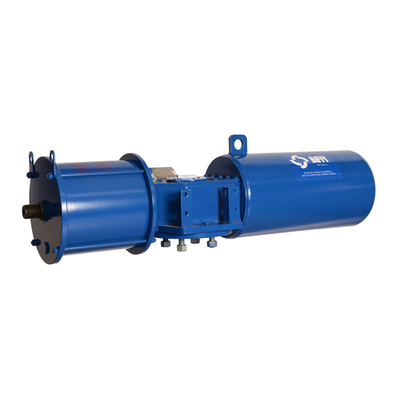
Spring-Return Pneumatic Actuator
Copyright © Biffi. The information in this document is subject to change without notice. Updated data sheets can be obtained from our website www.biffi.it or from your nearest Biffi Center:
Biffi Italia s.r.l. - Strada Biffi 165, 29017 Fiorenzuola d'Arda (PC) – Italy PH: +39 0523 944 411 – biffi_italia@biffi.it
Installation, Operation and Maintenance Manual
MAN 604A Rev. 5
June 2020
Advertisement
Table of Contents

Related Manuals for BIFFI ALGAS


Summary of Contents for BIFFI ALGAS
- Page 1 Spring-Return Pneumatic Actuator Copyright © Biffi. The information in this document is subject to change without notice. Updated data sheets can be obtained from our website www.biffi.it or from your nearest Biffi Center: Biffi Italia s.r.l. - Strada Biffi 165, 29017 Fiorenzuola d'Arda (PC) – Italy PH: +39 0523 944 411 – biffi_italia@biffi.it...
- Page 2 Revision Details Installation, Operation and Maintenance Manual June 2020 MAN 604A Rev. 5 Revision Details Rev. Date Description Prepared Checked Approved June 2020 General update (Migration to new template) March 2018 Updated data-plate Ermanni Orefici Vigliano April 2016 Updated applicable regulation (chapter 1.1.1) Ermanni Orefici Vigliano...
-
Page 3: Table Of Contents
Installation, Operation and Maintenance Manual Table of Contents MAN 604A Rev. 5 June 2020 Table of Contents Section 1: General Warnings Generalities ....................1 1.1.1 Applicable Regulation ................ 1 1.1.2 Terms and Conditions ................. 1 Identification Plate ..................2 Description of the Actuator ................2 Section 2: Installation Checks to Be Carried Out on Receiving the Actuator........ - Page 4 Table of Contents Installation, Operation and Maintenance Manual June 2020 MAN 604A Rev. 5 Section 5: Maintenance Routine Maintenance .................. 27 Extraordinary Maintenance ................. 28 5.2.1 Replacement of Cylinder Seals ............30 Lubrication of Mechanism ................34 Dismantling and Demolition ............... 35 Section 6: Troubleshooting Failure or Breakdown Research ..............
-
Page 5: Section 1: General Warnings
1.1.2 Terms and Conditions Biffi Italia s.r.l. guarantees that all the items produced are free of defects in workmanship and manufacturing materials and meet relevant current specifications, provided they are installed, used and serviced according to the instructions contained in the present manual. -
Page 6: Identification Plate
Identification Plate WARNING It is forbidden to modify the information and the marks without previous written authorization by Biffi Italia s.r.l. The plate fastened on the actuator contains the following information (Figure1). Description of the Actuator ALGAS low pressure pneumatic spring-return, are suitable for the operation of quarter-turn valves (ball valves, butterfly valves, plug valves) in both ON-OFF and modulating heavy-duty service. - Page 7 Installation, Operation and Maintenance Manual Section 1: General Warnings MAN 604A Rev. 5 June 2020 Table 1. Selection Guide Code: ALGAS XXX YYYYY ZZZZ Actuator series Scotch yoke mechanism size Yoke shape Canted Symmetric Spring cartridge size Cylinder size Internal diameter in mm...
-
Page 8: Section 2: Installation
Section 2: Installation Installation, Operation and Maintenance Manual June 2020 MAN 604A Rev. 5 Section 2: Installation Checks to Be Carried Out on Receiving the Actuator If the actuator arrives already assembled onto the valve, the settings of the mechanical stops and of the micro switches (if existing) has already been made by the person who assembled the actuator onto the valve. -
Page 9: Assembling The Actuator Onto The Valve
Types of Assembly For coupling to the valve, the housing is provided with a flange with threaded holes according to Biffi standard tables (SCN6200; SCN6200-1; SCN6201; SCN6201-1 SCN6201-3 SCN6201-5). The number, dimensions and diameter of the holes are made in accordance with ISO 5211, but for actuator models 0.3 to 6 the holes are drilled on the centreline in order to allow an easier assembly of an intermediate flange, when required. - Page 10 Section 2: Installation Installation, Operation and Maintenance Manual June 2020 MAN 604A Rev. 5 Figure 3 Drive sleeve Ø Ø +0.1 Ø ±0.2 Ø N. THREADED HOLES PCD, holes, number and size according to ISO 5211 (but the holes are on centerline instead of straddle the centerline) Flow line °...
- Page 11 Section 2: Installation Installation, Operation and Maintenance Manual MAN 604A Rev. 5 June 2020 Figure 4 Drive sleeve Ø Ø +0.1 Ø ±0.2 Ø N. THREADED HOLES PCD, holes, number and size according to ISO 5211 Flow line Ø +0.2 +0.1 Top view of the scotch yoke mechanism (actuator shown in closed position)
- Page 12 Section 2: Installation Installation, Operation and Maintenance Manual June 2020 MAN 604A Rev. 5 Figure 5 Drive sleeve Ø Ø +0.1 Ø ±0.2 Ø N. THREADED HOLES PCD, holes, number and size according to ISO 5211 Flow line Ø +0.2 +0.1 Top view of the scotch yoke mechanism (actuator shown in closed position)
- Page 13 Section 2: Installation Installation, Operation and Maintenance Manual MAN 604A Rev. 5 June 2020 Figure 6 Drive sleeve Ø Ø +0.1 Ø ±0.2 Ø N. THREADED HOLES Flow line Ø +0.2 +0.1 Top view of the scotch yoke mechanism (actuator shown in closed position) Table 6.
- Page 14 Section 2: Installation Installation, Operation and Maintenance Manual June 2020 MAN 604A Rev. 5 Figure 7 Drive sleeve Ø Ø +0.1 Ø ±0.2 Ø N. THREADED HOLES PCD, holes, number and size according to ISO 5211 Flow line Ø +0.2 +0.1 Top view of the scotch yoke mechanism (actuator shown in closed position)
- Page 15 Section 2: Installation Installation, Operation and Maintenance Manual MAN 604A Rev. 5 June 2020 Figure 8 Drive sleeve Ø Ø +0.1 Ø ±0.2 Ø N. THREADED HOLES PCD, holes, number and size according to ISO 5211 (but the holes are on centerline instead of straddle the centerline) Flow line Ø...
- Page 16 Insert bush turned upside down The Biffi insert bush with 2 external keys at 45° allows to position the keyway for the valve every 90°. Consequently actuator can be mounted in 4 positions at 90° on top of the valve.
-
Page 17: Valve Stem With Vertical Axis
Section 2: Installation Installation, Operation and Maintenance Manual MAN 604A Rev. 5 June 2020 2.3.2 Valve Stem with Vertical Axis NOTICE The lifting and handling of the actuator must be done by qualified personnel and in accordance with the laws and regulations in force. WARNING The actuator must be lifted by means of a suitable lifting apparatus. - Page 18 Installation, Operation and Maintenance Manual June 2020 MAN 604A Rev. 5 Lift ALGAS actuators (pneumatic spring-return) by means of the proper lifting points represented and indicated on actuator by sticking labels. Also refer to Figure 12 for lifting points positions.
- Page 19 June 2020 WARNING Any lifting method different from what described above is strictly forbidden. Biffi reject any responsibility for damages to goods or injuries to persons coming from wrong lifting operations. The actuator can be assembled onto the valve flange either by using the actuator-housing flange with threaded holes, or by the interposition of an adaptor flange or a spool piece.
- Page 20 Section 2: Installation Installation, Operation and Maintenance Manual June 2020 MAN 604A Rev. 5 Connect a sling to the support points of the actuator and lift it: make sure the sling is suitable for the actuator weight. When possible, it is easier to assemble the actuator to the valve if the valve stem is in the vertical position.
-
Page 21: Valve Stem With Horizontal Axis
Section 2: Installation Installation, Operation and Maintenance Manual MAN 604A Rev. 5 June 2020 2.3.3 Valve Stem with Horizontal Axis The actuator can also be lifted to assemble directly onto the valve with stem with horizontal axis. To make a correct lifting procedure proceed as follow: Connect properly the actuator lifting points 1 with chains, and connect by suitable slings the support brackets 2 and 3. - Page 22 Section 2: Installation Installation, Operation and Maintenance Manual June 2020 MAN 604A Rev. 5 Balance the weight and lift the actuator until to make possible the rotation of actuator in its final mounting position, with cylinder on top, or spring container placed on top, as showed in the following figures.
-
Page 23: Section 3: Operation And Use
Installation, Operation and Maintenance Manual Section 3: Operation and Use MAN 604A Rev. 5 June 2020 Section 3: Operation and Use Setting of the Angular Stroke It is important that the mechanical stops of the actuator (and not those of the valve) stop the angular stroke at both extreme valve position (fully open and fully closed), except when this is required by the valve operation (e.g. - Page 24 Section 3: Operation and Use Installation, Operation and Maintenance Manual June 2020 MAN 604A Rev. 5 Figure 16 Table 11. Pneumatic cylinder size Wrench c1 (mm) Wrench c2 (mm) Table 12. Pneumatic cylinder size Wrench c1 (mm) Wrench c2 (mm) 1000 1100 1200...
-
Page 25: Stop Screw Screwed On The End Flange Of Spring Container
Installation, Operation and Maintenance Manual Section 3: Operation and Use MAN 604A Rev. 5 June 2020 3.1.2 Stop Screw Screwed on the End Flange of Spring Container For the adjustment of the travel stop screw, for model from 006 to 150, proceed as follows: Figure 17 For the adjustment of the travel stop screw, for model from 200 to 19600, proceed as follows:... - Page 26 Section 3: Operation and Use Installation, Operation and Maintenance Manual June 2020 MAN 604A Rev. 5 To operate the adjustments, refer to following Tables: Table 13. Spring container size Wrench c1 (mm) Wrench c2 (mm) 0100 0150 Table 14. Spring container size Wrench c1 (mm) Wrench c2 (mm) 0200...
-
Page 27: Calibration Of Micro-Switches (If Foreseen)
Calibration of Operating Time The calibration of the operation time is made by Biffi Italia s.r.l according to customer requirements and to technical data sheet included in technical documentation. If necessary, it’s possible to modify or to reset the operating time through the flow regulation valve placed between the control system and the pneumatic cylinder (Figure 19). -
Page 28: Preparation For Start-Up
NOTICE If necessary to mount components not in Biffi scope of supply, please check the accessories mounting hole details in the documents TN 1028 (for metric dimension) or TN 1028U (for imperial dimension). -
Page 29: Electrical Connections
Installation, Operation and Maintenance Manual Section 3: Operation and Use MAN 604A Rev. 5 June 2020 3.4.2 Electrical Connections Connect the electrical feed, control and signal lines to the actuator, by linking them up with the terminal blocks of the electrical components. In order to do this, the housing covers must be removed without damaging the coupling surfaces, the O-rings or the gaskets. -
Page 30: Section 4: Operational Tests And Inspections
Section 4: Operational Tests and Inspections Installation, Operation and Maintenance Manual June 2020 MAN 604A Rev. 5 Section 4: Operational Tests and Inspections NOTICE To ensure the guaranteed SIL grade, according to IEC 61508, the functionality of actuator must be checked with regular intervals of time, as described in the Safety Manual. Operational Tests and Inspections... -
Page 31: Section 5: Maintenance
Installation, commissioning and maintenance and repair works should be carried out by qualified staff. Routine Maintenance ALGAS actuators have been designed to work for long periods in the severest conditions with no need for maintenance. NOTICE Periodicity and regularity of inspections is particularly influenced by specific environmental and working conditions. -
Page 32: Extraordinary Maintenance
Section 5: Maintenance Installation, Operation and Maintenance Manual June 2020 MAN 604A Rev. 5 Extraordinary Maintenance If there are leaks in the hydraulic cylinder, pneumatic cylinder or a malfunction in the mechanical components, or in case of scheduled preventive maintenance, the actuator must be disassembly and seals must be replaced with reference to the follow general sectional drawing and adopting the following procedures. - Page 33 Section 5: Maintenance Installation, Operation and Maintenance Manual MAN 604A Rev. 5 June 2020 Figure 21 Table 15. Dimension "X" (spring side) Dimension "Y" (cylinder side) Model size 32 - 42 1000 50 - 60 1200 65 - 55 1200 1100 1400 Maintenance...
-
Page 34: Replacement Of Cylinder Seals
Section 5: Maintenance Installation, Operation and Maintenance Manual June 2020 MAN 604A Rev. 5 5.2.1 Replacement of Cylinder Seals Refer to the following sectional drawing. Measure the protrusion of the stop screw (26) with reference to the end flange (22) surface, so as to be able to easily restore the setting of the actuator mechanical stop, once the maintenance procedures have been completed. - Page 35 Installation, Operation and Maintenance Manual Section 5: Maintenance MAN 604A Rev. 5 June 2020 5.2.1.2 Cylinder Reassembling Carefully clean the inside of the tube (19) and check that the entire surface, particularly that of the bevels, is not damaged. Lubricate the inside surface of the tube and the bevels at the ends.
- Page 36 Section 5: Maintenance Installation, Operation and Maintenance Manual June 2020 MAN 604A Rev. 5 Figure 22 Table 16. Item Description Stop setting screw Spring container Spring Shoulder washer Rod bushing Screw Housing Guide bar Cover gasket Yoke Plug Bushing Guide block Screw Head flange Tie rod...
- Page 37 Installation, Operation and Maintenance Manual Section 5: Maintenance MAN 604A Rev. 5 June 2020 Item Description Cylinder tube Piston rod Piston End flange Lifting eyelet Spring washer Stop setting screw Guide rod Spring thrust flange Rod bushing Container rod Adaptor bush Washer Cover Screw...
-
Page 38: Lubrication Of Mechanism
It’s necessary restore the grease into spring cartridge (for this operation remove the plug on end-flange of spring cartridge and restore a generous coating of grease) The following grease is used by Biffi for standard working temperature and suggested for re-lubrication: Table 17. -
Page 39: Dismantling And Demolition
Installation, Operation and Maintenance Manual Section 5: Maintenance MAN 604A Rev. 5 June 2020 Dismantling and Demolition Before starting the disassembly a large area should be created around the actuator so to allow any kind of movement without problems of further risks created by worksite. WARNING Before disassembling the actuator it is necessary to close the pneumatic feed line and discharge pressure from the cylinder of the actuator, from the control unit and from the... -
Page 40: Section 6: Troubleshooting
Wrong position of the distributor of not work Restore correct position the manual hydraulic group Failure of the control group Call Biffi Italia s.r.l. Customer Service Low supply pressure Restore (Section 1.4) Low supply pressure Restore (Section 1.4) Actuator too slow Wrong calibration of flow regulator valves Restore (Section 3.6) -
Page 41: Section 7: Layouts And Sectional Drawings
* Recommended spare parts Cycles performed by actuator in a 25 years expected lifetime - the minimum performed cycles are guarantied by Biffi based on service conditions listed: — All the valve required torques have to be lower than actuator max operating torque (MOT). - Page 42 * Recommended spare parts Cycles performed by actuator in a 25 years expected lifetime - the minimum performed cycles are guarantied by Biffi based on service conditions listed: — All the valve required torques have to be lower than actuator max operating torque (MOT).
- Page 43 Installation, Operation and Maintenance Manual Section 7: Layouts and Sectional Drawings MAN 604A Rev. 5 June 2020 Figure 25 Pneumatic cylinder Table 21. Parts list Item Description Material Piston rod bushing Steel + bronze + PTFE O-ring * NBR O-ring * NBR Head flange Carbon steel...
- Page 44 Section 7: Layouts and Sectional Drawings Installation, Operation and Maintenance Manual June 2020 MAN 604A Rev. 5 Figure 26 Spring cartridge Table 22. Parts list Item Description Material Carbon steel Washer Carbon steel Sealing washer * PVC Stop setting screw Carbon steel Spring container Carbon steel...
- Page 45 Installation, Operation and Maintenance Manual Section 7: Layouts and Sectional Drawings MAN 604A Rev. 5 June 2020 Figure 27 Assembly kit Spring to close assembly Spring to open assembly Table 23. Parts list Item Description Material Screw Alloy steel Gasket * SBR + Cellulose + fillers Plug Carbon steel...
-
Page 46: Section 8: Spare Parts
MAN 604A Rev. 5 Section 8: Spare Parts For spare parts order to the relevant Biffi office please make reference to Biffi order confirmation concerning all the supply, and serial number of the actuator (Section 1.2) for any specific spare part for a specific actuator model. -
Page 47: Section 9: Date Report For Maintenance Operations
Installation, Operation and Maintenance Manual Section 9: Date Report for Maintenance Operations MAN 604A Rev. 5 June 2020 Section 9: Date Report for Maintenance Operations Last maintenance operation date: (in factory, on delivery): ……… exec. by : ………… ……… exec. by : ………… ………... - Page 48 VCIOM-03198-EN ©2020 Biffi. All rights reserved. Biffi Italia s.r.l. Strada Biffi 165 The contents of this publication are presented for information purposes only, 29017 Fiorenzuola d’Arda (PC) and while every effort has been made to ensure their accuracy, they are not...
Need help?
Do you have a question about the ALGAS and is the answer not in the manual?
Questions and answers