Table of Contents
Advertisement
Quick Links
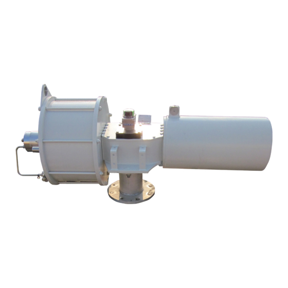
Biffi ALGAS-QA EAC
"Quick Acting" Spring-Return Pneumatic Actuator
Copyright © Biffi. The information in this document is subject to change without notice. Updated data sheets can be obtained from our website www.biffi.it or from your nearest Biffi Center:
Biffi Italia s.r.l. - Strada Biffi 165, 29017 Fiorenzuola d'Arda (PC) – Italy PH: +39 0523 944 411 – biffi_italia@biffi.it
Installation, Operation and Maintenance Manual
MAN616_EAC Rev. 5
July 2020
Advertisement
Table of Contents

Related Manuals for BIFFI ALGAS-QA EAC


Summary of Contents for BIFFI ALGAS-QA EAC
- Page 1 “Quick Acting” Spring-Return Pneumatic Actuator Copyright © Biffi. The information in this document is subject to change without notice. Updated data sheets can be obtained from our website www.biffi.it or from your nearest Biffi Center: Biffi Italia s.r.l. - Strada Biffi 165, 29017 Fiorenzuola d'Arda (PC) – Italy PH: +39 0523 944 411 – biffi_italia@biffi.it...
- Page 2 Revision Details Installation, Operation and Maintenance Manual July 2020 MAN616_EAC Rev. 5 Revision Details Rev. Date Description Prepared Checked Approved July 2020 General update (Migration to new template) March 2018 Updated Section 2.2 Ermanni Orefici Vigliano Updated applicable regulation January 2017 Ermanni Orefici Vigliano...
-
Page 3: Table Of Contents
End Flange of Pneumatic Cylinder ........... 24 3.5.3 Stop Screw Screwed on the End Flange of Spring Container ....25 Calibration of Micro-switches (Applicable to Biffi Limit Switch Box Model Only) ..27 Preparation for Start-up ................29 3.7.1 Pneumatic Connections .............. - Page 4 Table of Contents Installation, Operation and Maintenance Manual July 2020 MAN616_EAC Rev. 5 Section 5: Maintenance Routine Maintenance ................. 32 Extraordinary Maintenance ................ 33 5.2.1 Replacement of Cylinder Seals ............34 5.2.1.1 Seals Replacement................34 5.2.1.2 Cylinder Reassembling ..............35 Lubrication of Mechanism ................
-
Page 5: Section 1: General Warnings
Biffi Italia s.r.l. will not be responsible for any mistakes contained in it or for any damage either accidental or due to the use of this manual. The information herein contained is reserved property of Biffi Italia s.r.l. and is subject to being modified without notice. -
Page 6: Terms And Conditions
1.1.2 Terms and Conditions Biffi Italia s.r.l. guarantees that all the items produced are free of defects in workmanship and manufacturing materials and meet relevant current specifications, provided they are installed, used and serviced according to the instructions contained in the present manual. -
Page 7: Description Of The Actuator
The actuator yoke has a hole with keyways suitable for the assembly of an insert bush or a stem extension. Their internal hole is machined (by BIFFI or at Customer's care), according to the shape and dimensions of the valve stem. - Page 8 Section 1: General Warnings Installation, Operation and Maintenance Manual July 2020 MAN616_EAC Rev. 5 Table 1. Single Acting Pneumatic Actuators ALGAS Series - Coding System Code: ALGAS YYYYY ZZZZ Actuator series Actuator model Scotch yoke version Canted Symmetric Spring cartridge model Cylinder size Internal diameter in mm Fail safe action...
-
Page 9: Section 2: Installation
Installation, Operation and Maintenance Manual Section 2: Installation MAN616_EAC Rev. 5 July 2020 Section 2: Installation Checks to be Carried Out on Receiving the Actuator If the actuator arrives already assembled onto the valve, the settings of the mechanical stops and of the micro-switches (if existing) has already been made by the person who assembled the actuator onto the valve. -
Page 10: Assembling The Actuator Onto The Valve
Types of Assembly For coupling to the valve, the housing is provided with a flange with threaded holes according to Biffi standard tables (SCN6200; SCN6200-1; SCN6201; SCN6201-1). The number, dimensions and diameter of the holes are made in accordance with ISO 5211, but for actuator models 0.3 to 6 the holes are drilled on the centreline in order to allow... - Page 11 Installation, Operation and Maintenance Manual Section 2: Installation MAN616_EAC Rev. 5 July 2020 Figure 2 Coupling Dimensions for Scotch Yoke Standard Actuators Models from 0.3 to 6 Drive sleeve ø d1 max N. THREADED HOLES P.C.D., number and size according to ISO 5211 (but the holes are on centerline instead of straddle the centerline) Flow line...
- Page 12 Section 2: Installation Installation, Operation and Maintenance Manual July 2020 MAN616_EAC Rev. 5 Figure 3 Coupling Dimensions for Scotch Yoke Standard Actuators Models 14, 18, 32, 35, 42 Drive sleeve ø d1 max N. THREADED HOLES P.C.D., number and size according to ISO 5211 Flow line Top view of the scotch yoke mechanism...
- Page 13 Installation, Operation and Maintenance Manual Section 2: Installation MAN616_EAC Rev. 5 July 2020 Figure 4 Coupling Dimensions for Scotch Yoke Standard Actuators Models 50, 60 Drive sleeve ø d1 max N. THREADED HOLES Flange sizing according to ISO Flow line Top view of the scotch yoke mechanism (actuator shown in closed position) Table 4.
- Page 14 Insert bush turned upside down The Biffi insert bush with 2 external keys at 45° allows to position the keyway for the valve every 90°. Consequently actuator can be mounted in 4 positions at 90° on top of the valve.
-
Page 15: Valve Stem With Vertical Axis
Installation, Operation and Maintenance Manual Section 2: Installation MAN616_EAC Rev. 5 July 2020 2.3.2 Valve Stem with Vertical Axis NOTICE The lifting and handling of the actuator must be done by qualified personnel and in accordance with the laws and regulations in force. Avoid the lifted actuator to be hung above the personnel. WARNING The actuator must be lifted by means of a suitable lifting apparatus. - Page 16 Section 2: Installation Installation, Operation and Maintenance Manual July 2020 MAN616_EAC Rev. 5 Lift ALGAS-QA actuators (pneumatic spring-return) by means of the proper lifting points represented and indicated on actuator by sticking labels. Also refer to figures 8 for lifting points positions.
- Page 17 WARNING Any lifting method different from what described above is strictly forbidden. Biffi reject any responsibility for damages to goods or injuries to persons coming from wrong lifting operations. The actuator can be assembled onto the valve flange either by using the actuator-housing flange with threaded holes, or by the interposition of an adaptor flange or a spool piece.
- Page 18 Section 2: Installation Installation, Operation and Maintenance Manual July 2020 MAN616_EAC Rev. 5 Connect a sling to the support points of the actuator and lift it: make sure the sling is suitable for the actuator weight. When possible, it is easier to assemble the actuator to the valve if the valve stem is in the vertical position.
-
Page 19: Valve Stem With Horizontal Axis
Installation, Operation and Maintenance Manual Section 2: Installation MAN616_EAC Rev. 5 July 2020 2.3.3 Valve Stem with Horizontal Axis The actuator can also be lifted to assemble directly onto the valve with stem with horizontal axis. To make a correct lifting procedure proceed as follow: Connect properly the actuator lifting points 1 with chains, and connect by suitable slings the support brackets 2 and 3. - Page 20 Section 2: Installation Installation, Operation and Maintenance Manual July 2020 MAN616_EAC Rev. 5 Balance the weight and lift the actuator until to make possible the rotation of actuator in its final mounting position, with cylinder on top, or spring container placed on top, as showed in the following images: Figure 11 PLAS MHP Without Control System...
-
Page 21: Section 3: Operation And Use
Installation, Operation and Maintenance Manual Section 3: Operation and Use MAN616_EAC Rev. 5 July 2020 Section 3: Operation and Use Operation Description The actuator is operated by: Pressurized motor fluid. Elastic return of compression helicoidally spring. In the first case the alimentation fluid pressurizes a chamber of the cylinder and compresses the spring (Figure 13);... -
Page 22: Residual Risks
Section 3: Operation and Use Installation, Operation and Maintenance Manual July 2020 MAN616_EAC Rev. 5 Figure 13 Generic Operating Diagram Pneumatic supply connection single acting spring-return pneumatic actuator electric micro-switches 124 check valve 276 bidirectional flow regulator (adjustable setting) 285 adjustable quick exhaust valve with external pilot Electric connection with micro-switches Pneumatic Control to Open Pressurize permanently the pneumatic supply line. -
Page 23: Calibration Of The Quick Operation Time
(Figure 14). The calibration of the operation time is made by Biffi Italia s.r.l. according to customer requirements and to technical data-sheet included in technical documentation. - Page 24 Section 3: Operation and Use Installation, Operation and Maintenance Manual July 2020 MAN616_EAC Rev. 5 3.4.1 By-pass Adjustment Figure 15 By-pass Action to Angular Stroke / Quick Operation Time Diagram Angular stroke/quick operation time diagram Two by-pass valves open One by-pass valve open Two by-pass valves closed Time (ms) Remove the protection cap from adjusting needle-valve and turn it clockwise to increase...
-
Page 25: Setting Of The Angular Stroke
Installation, Operation and Maintenance Manual Section 3: Operation and Use MAN616_EAC Rev. 5 July 2020 Setting of the Angular Stroke It is important that the mechanical stops of the actuator (and not those of the valve) stop the angular stroke at both extreme valve position (fully open and fully closed), except when this is required by the valve operation (e.g. - Page 26 Section 3: Operation and Use Installation, Operation and Maintenance Manual July 2020 MAN616_EAC Rev. 5 Figure 16 Table 7. Pneumatic Cylinder Size Wrench C1 (mm) Wrench C2 (mm) Operation and Use...
- Page 27 Installation, Operation and Maintenance Manual Section 3: Operation and Use MAN616_EAC Rev. 5 July 2020 Figure 17 Table 8. Pneumatic Cylinder Size Wrench C1 (mm) Wrench C2 (mm) 1000 1100 1200 1300 1450 Operation and Use...
-
Page 28: Angular Stroke Setting In Case Of Two Travel Stop Screws In The End Flange Of Pneumatic Cylinder
Section 3: Operation and Use Installation, Operation and Maintenance Manual July 2020 MAN616_EAC Rev. 5 3.5.2 Angular Stroke Setting in Case of Two Travel Stop Screws in the End Flange of Pneumatic Cylinder WARNING Do not change the setting in case of disassembly of the actuator of the valve. To set the two travel stop screws in the flange of the pneumatic cylinder, proceed as follows: (see Figure 18 and table 9 on page 26) Supply pressure to the cylinder to reduce trust on the stop screws. -
Page 29: Stop Screw Screwed On The End Flange Of Spring Container
Installation, Operation and Maintenance Manual Section 3: Operation and Use MAN616_EAC Rev. 5 July 2020 Figure 19 Reduce or stop cylinder supply to verify the angular stroke. Repeat operation until the required angular stroke is attained. Tighten the two lock nuts (d). 3.5.3 Stop Screw Screwed on the End Flange of Spring Container For the adjustment of the travel stop screw proceed as follows:... - Page 30 Section 3: Operation and Use Installation, Operation and Maintenance Manual July 2020 MAN616_EAC Rev. 5 Loosen the lock nut “d”. If the actuator angular stroke is stopped before reaching the end position, unscrew the stop screw “v” by turning it anticlockwise until the valve reaches the correct position.
-
Page 31: Calibration Of Micro-Switches (Applicable To Biffi Limit Switch Box Model Only)
Installation, Operation and Maintenance Manual Section 3: Operation and Use MAN616_EAC Rev. 5 July 2020 Calibration of Micro-switches (If Foreseen) (Refer to Safety Instructions Manual for limit switch box) WARNING Refer only to technical documentation related to installed switch-box model. NOTICE For mounting interface dimension of the Limit Switch box on the cover of the actuator, please refer to TN1163V (for metric dimension) or TN1163VU (for imperial dimension). - Page 32 Section 3: Operation and Use Installation, Operation and Maintenance Manual July 2020 MAN616_EAC Rev. 5 Figure 22 Micro-switches Box Figure 23 Cam Adjustment If the index (Figure 22), does not signal the proper position of the valve but is turned by 90°: •...
-
Page 33: Preparation For Start-Up
NOTICE If necessary to mount components not in Biffi scope of supply please check the accessories mounting hole details in the documents TN 1028 ( for metric dimension) or TN 1028U (for imperial dimension) 3.7.2... -
Page 34: Start-Up
Section 3: Operation and Use Installation, Operation and Maintenance Manual July 2020 MAN616_EAC Rev. 5 Start-up During the start-up of the actuator, proceed as follows: Check that the pressure and quality of the air supply (filtering degree, dehydration) are as prescript. Check that the feed voltage values of the electric components (solenoid valve coils, micro-switches, pressure switches, etc.) are as prescript. -
Page 35: Section 4: Operational Tests And Inspections
Installation, Operation and Maintenance Manual Section 4: Operational Tests and Inspections MAN616_EAC Rev. 5 July 2020 Section 4: Operational Tests and Inspections NOTICE To ensure the guaranteed SIL grade, according to IEC 61508, the functionality of actuator must be checked with regular intervals of time, as described in the Safety Manual. Operational Tests and Inspections... -
Page 36: Section 5: Maintenance
Section 5: Maintenance Installation, Operation and Maintenance Manual July 2020 MAN616_EAC Rev. 5 Section 5: Maintenance NOTICE Before carrying out any maintenance operation, it is necessary to close the pneumatic feed line and exhaust the pressure from the actuator cylinder and from the control unit, to ensure safety of maintenance staff. -
Page 37: Extraordinary Maintenance
Installation, Operation and Maintenance Manual Section 5: Maintenance MAN616_EAC Rev. 5 July 2020 Extraordinary Maintenance If there are leaks in the hydraulic cylinder, pneumatic cylinder or a malfunction in the mechanical components, or in case of scheduled preventive maintenance, the actuator must be disassembled and seals must be replaced with reference to the follow general sectional drawing and adopting the following procedures. -
Page 38: Replacement Of Cylinder Seals
Section 5: Maintenance Installation, Operation and Maintenance Manual July 2020 MAN616_EAC Rev. 5 5.2.1 Replacement of Cylinder Seals Refer to the following sectional drawing. Measure the protrusion of the stop screw (26) with reference to the end flange (22) surface, so as to be able to easily restore the setting of the actuator mechanical stop, once the maintenance procedures have been completed. -
Page 39: Cylinder Reassembling
Installation, Operation and Maintenance Manual Section 5: Maintenance MAN616_EAC Rev. 5 July 2020 5.2.1.2 Cylinder Reassembling Carefully clean the inside of the tube (19) and check that the entire surface, particularly that of the bevels, is not damaged. Lubricate the inside surface of the tube and the bevels at the ends. - Page 40 Section 5: Maintenance Installation, Operation and Maintenance Manual July 2020 MAN616_EAC Rev. 5 Figure 26 ALGAS - QA "Quick - acting" spring-return pneumatic actuator Maintenance...
- Page 41 Installation, Operation and Maintenance Manual Section 5: Maintenance MAN616_EAC Rev. 5 July 2020 Table 10. Parts LIst Item Description Item Description Stop setting screw Retainer ring Spring container Spring Washer Sealing washer Shoulder washer Gasket Rod bushing piston rod bushing Screw O - ring Housing...
-
Page 42: Lubrication Of Mechanism
For this operation it is necessary to disassemble the mechanism cover. In larger actuators the lubrication can be performed through the inspection holes of the cover after removing the plugs. The following grease is used by Biffi for standard working temperature and suggested for re-lubrication: Table 11. -
Page 43: Dismantling And Demolition
Installation, Operation and Maintenance Manual Section 5: Maintenance MAN616_EAC Rev. 5 July 2020 Dismantling and Demolition Before starting the disassembly a large area should be created around the actuator so to allow any kind of movement without problems of further risks created by work-site. WARNING Before disassembling the actuator it is necessary to close the pneumatic feed line and discharge pressure from the cylinder of the actuator, from the control unit and from the... -
Page 44: Section 6: Troubleshooting
Wrong position of the distributor Restore correct position Actuator does not work of the hydraulic manual override Failure of the spring Call Biffi Italia s.r.l. Customer Service Failure of the control group Call Biffi Italia s.r.l. Customer Service Low supply pressure Restore (Section 1.4) Low supply pressure Restore (Section 1.4) -
Page 45: Section 7: Layouts And Sectional Drawings
Installation, Operation and Maintenance Manual Section 7: Layouts and Sectional Drawings MAN616_EAC Rev. 5 July 2020 Section 7: Layouts and Sectional Drawings Parts List for Maintenance and Replacing Procedure Figure 27 Scotch Yoke Mechanism Table 13. Parts List Item Description Material O - ring * Fluorosilicon rubber... - Page 46 Section 7: Layouts and Sectional Drawings Installation, Operation and Maintenance Manual July 2020 MAN616_EAC Rev. 5 Figure 28 Pneumatic Cylinder Table 14. Parts List Item Description Material Piston rod bushing Steel + BZ + Teflon O - ring * Fluorosilicon rubber O - ring * Fluorosilicon rubber Head flange...
- Page 47 Installation, Operation and Maintenance Manual Section 7: Layouts and Sectional Drawings MAN616_EAC Rev. 5 July 2020 Figure 29 Spring Cartridge Table 15. Parts List Item Description Material Nitrided carbon steel Washer Carbon steel Sealing washer * Elvax Stop setting screw Nitrided carbon steel Spring container Carbon steel...
- Page 48 Section 7: Layouts and Sectional Drawings Installation, Operation and Maintenance Manual July 2020 MAN616_EAC Rev. 5 Figure 30 Assembly Kit Spring to open assembly Spring to close assembly Table 16. Parts List Item Description Material Screw Alloy steel Gasket * SBR + cellulose + filler Plug Carbon steel Adaptor bush...
- Page 49 Installation, Operation and Maintenance Manual Section 7: Layouts and Sectional Drawings MAN616_EAC Rev. 5 July 2020 Figure 31 Quick Exhaust Valve Part A Part A Layouts and Sectional Drawings...
- Page 50 Section 7: Layouts and Sectional Drawings Installation, Operation and Maintenance Manual July 2020 MAN616_EAC Rev. 5 Table 17. Parts List Item Description Material Spacer Stainless steel O - ring * Viton Piston ring nut Stainless steel Piston Aluminium O - ring * Viton Filter Stainless steel...
-
Page 51: Section 8: Spare Parts
Section 8: Spare Parts Spare Parts Order For spare parts order to the relevant Biffi office please make reference to Biffi order confirmation concerning all the supply, and serial number of the actuator, refer to Section 1.2 for any specific spare part for a specific actuator model. -
Page 52: Section 9: Date Report For Maintenance Operations
Section 9: Date Report for Maintenance Operations Installation, Operation and Maintenance Manual July 2020 MAN616_EAC Rev. 5 Section 9: Date Report for Maintenance Operations Last maintenance operation date: (in factory, on delivery): ……… exec. by : ………… ……… exec. by : ………… ………... - Page 53 Installation, Operation and Maintenance Manual Notes MAN616_EAC Rev. 5 July 2020 This page intentionally left blank Notes...
- Page 54 VCIOM-15570-EN ©2020 Biffi. All rights reserved. Biffi Italia s.r.l. Strada Biffi 165 The contents of this publication are presented for information purposes only, 29017 Fiorenzuola d’Arda (PC) and while every effort has been made to ensure their accuracy, they are not...
Need help?
Do you have a question about the ALGAS-QA EAC and is the answer not in the manual?
Questions and answers