Table of Contents
Advertisement
Quick Links
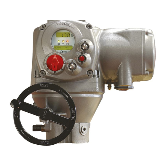
BIFFI F01-2000 ELECTRIC ACTUATOR
INSTRUCTION AND OPERATING MANUAL
GENERAL INSTRUCTIONS FOR INSTALLATION
OPERATION AND CONFIGURATION
www�biffi�it
MAINTENANCE AND TROUBLESHOOTING
SPARE PARTS AND DRAWINGS
Copyright © Biffi. All rights reserved.
INDEX
1
General safety instructions ������������������� 2
1.1
Range of application ................................. 2
1.2
hazardous area ......................................... 2
1.3
1.4
Terms and conditions ............................... 3
1.5
Identification of the main parts ................ 3
2
Storage and pre-installation ����������������� 4
2.1
Tests to be carried out when
the actuator is received ............................ 4
2.2
Storage procedure .................................... 4
2.3
before installation ..................................... 5
3
Installation �������������������������������������������� 5
3.1
Working condition ..................................... 5
3.2
the actuator ............................................... 5
3.3
Manual operation ...................................... 6
3.4
Mounting the actuator onto the valve ...... 7
3.5
Electrical connections .............................. 7
3.6
covers ......................................................... 8
3.7
Cable entries ............................................. 8
3.8
Terminal board .......................................... 9
3.9
enclosures ................................................. 9
explosive dusts ........................................ 10
4
Lubrication ������������������������������������������ 10
4.1
Lubrication inspection ............................ 10
5
Operating the F01-2000 ���������������������� 11
5.1
Operation by handwheel ......................... 11
5.2
Setting of mehanical stops ..................... 11
5.3
Electrical operation ................................. 12
5.4
Local control............................................ 12
5.5
Local indication ....................................... 12
5.6
Lock of the 3-position selector .............. 12
5.7
Remote control........................................ 13
5.8
5.9
Optional modules .................................... 14
5.10 Base card of the F01-2000 v4 ................. 16
VCIOM-01249-EN 17/12
Advertisement
Table of Contents

Related Manuals for BIFFI F01-2000


Summary of Contents for BIFFI F01-2000
-
Page 1: Table Of Contents
Local indication ........12 Lock of the 3-position selector ....12 Remote control........13 Operating the F01-2000 for the first time .. 14 Optional modules ........14 5.10 Base card of the F01-2000 v4 ....16 www�biffi�it VCIOM-01249-EN 17/12 Copyright © Biffi. All rights reserved. -
Page 2: General Safety Instructions
Category 2 apparatus chemical and petrochemical plants. Explosive atmospheres caused View menu ������������������������������������������� 25 Biffi will not be liable for any possible damage by gas, mists or vapors resulting from use in other than the designated Explosive atmospheres caused Set-up routines ����������������������������������� 27 applications. -
Page 3: Applicable Standards And Regulations
1�4 TERMS AND CONDITIONS Hazardous zone Zone Categories according to 94/9/EC Directive Gas, mists or vapors Biffi guarantees each single product to be free Gas, mists or vapors 2G or 1G from defects and to conform to current goods Gas, mists or vapors 3G or 2G or 1G specifications. -
Page 4: Storage And Pre-Installation
Biffi actuators are weatherproof to IP68 for a submersion at depth of 15 metres for 90 hours. This condition can only be maintained if the units are correctly installed/connected on site and if they have been correctly stored. -
Page 5: Checks To Be Performed Before Installation
BIFFI F01-2000 ELECTRIC ACTUATOR INSTRUCTION AND OPERATING MANUAL 3 INSTALLATION 3�1 WORKING CONDITION The standard actuators are suitable for the following environment temperatures: -30°C +85°C (-22°F to +185°F) Special versions are available for extreme environment temperatures: -40°C +70°C (-40°F to +158°F) -55°C +70°C (-67°F to +158°F) -
Page 6: Manual Operation
BIFFI F01-2000 ELECTRIC ACTUATOR INSTRUCTION AND OPERATING MANUAL 3�3 MANUAL OPERATION To manually operate the actuator it is sufficient to turn the handwheel in the desired direction. WARNING Do not manually operate the actuator with devices other than the handwheel. -
Page 7: Mounting The Actuator Onto The Valve
Lift the actuator with slings suitable for its covers without Biffi’s approval will invalidate weight. the warranty. Biffi will not accept any responsibility for any Check the dimensions of the valve mounting damage or deterioration that may be caused. details, paying particular attention to the... -
Page 8: Removing The Electrical Enclosures' Covers
BIFFI F01-2000 ELECTRIC ACTUATOR INSTRUCTION AND OPERATING MANUAL 3�6 REMOVING THE ELECTRICAL To guarantee weatherproof and explosionproof ENCLOSURES’ COVERS fit, screw the cable glands tightly (at least 5 turns) and block them with a thread sealant. Using a 8 mm Allen key, loosen the four screws The use of a thread sealant is necessary in case and remove the cover. -
Page 9: Terminal Board
(covers, cable glands, joints) be careful to bring 3�8 TERMINAL BOARD these enclosures back to their original condition IMPORTANT The removal of any other covers without Biffi’s CONNECTION TABLE approval will invalidate the warranty. Biffi will not accept any responsibility for any damage or... -
Page 10: Installation In Environment With Explosive Dusts
IP68 protection degree, can be used. 3�10 INSTALLATION IN ENVIRONMENT WITH EXPLOSIVE DUSTS IMPORTANT Electric actuator F01-2000 shall be installed and maintained according to the applicable rules regarding the electrical installations in hazardous area (other than mines) classified as zone 21 (dust);... -
Page 11: Operating The F01-2000
BIFFI F01-2000 ELECTRIC ACTUATOR INSTRUCTION AND OPERATING MANUAL Before any setting operation, it is necessary to unscrew the adjustable mechanical stops. Hold the lock nut and remove the mechanical stop protection by unscrewing it. Remove the seal washer. 5 OPERATING THE F01-2000 5�1 OPERATION BY HANDWHEEL... -
Page 12: Electrical Operation
BIFFI F01-2000 ELECTRIC ACTUATOR INSTRUCTION AND OPERATING MANUAL 5�5 LOCAL INDICATION The upper display (3½ LCD) indicates the valve position as a percentage of opening OPEN/YES (open = 100%). The lower display has two alphanumeric lines. The upper line indicates the actuator status and the 3-position selector status. -
Page 13: Remote Control
BIFFI F01-2000 ELECTRIC ACTUATOR INSTRUCTION AND OPERATING MANUAL 5�7 REMOTE CONTROL - Minimum signal duration > 300 ms. OPTION A1) - Total current drawn from remote controls Place the 3-position selector in REMOTE to < 25 mA transfer the actuator control to a remote 5�7�2 Output contacts... -
Page 14: Operating The F01-2000 For The First Time
The interlock controls work If the following message appears, the base when the local selector is in either LOCAL card is F01-2000 v4 type, but the actuator is OPTION D2) or REMOTE positions. The ESD control equipped with an F01-2000 v0 series terminal overrides the interlock controls. - Page 15 4-20 mA will not be updated. • 4-20 mA analog input The 4-20 mA analog input is the position request R% signal and is used by the F01-2000 to position the valve in inching and modulating actuators. The “POSITIONER” routine...
-
Page 16: Base Card Of The F01-2000 V4
BIFFI F01-2000 ELECTRIC ACTUATOR INSTRUCTION AND OPERATING MANUAL 5�10 BASE CARD OF THE F01-2000 V4 Ain/Aout card This optional card is used in place of the Terminal Board Adaptor (TBA) card when an analog 4-20 mA input and output signal is requested. -
Page 17: Local Controls
- actuator configuration to view and change the actuator configuration - actuator status visualisation The F01-2000 can be provided with a or to scroll the list of variables, status, and The figures on the following pages describe radiofrequency wireless connection based on alarms. - Page 18 BIFFI F01-2000 ELECTRIC ACTUATOR INSTRUCTION AND OPERATING MANUAL DESCRIPTION OF VARIABLES AND REPORTS torque output torque in % of the nominal torque stated in the NAMEPLATE menu motor speed RPM of electrical motor main voltage voltage (V) and frequency (Hz) of mains...
- Page 19 BIFFI F01-2000 ELECTRIC ACTUATOR INSTRUCTION AND OPERATING MANUAL The following drawing shows the use of the OPEN / YES, CLOSE / NO and STOP push-buttons in function of the local selector position. LOCAL REMOTE 3-POSITION SELECTOR = OPEN/YES push-button = CLOSE/NO push-button...
-
Page 20: Configuration Options
The parameters appear on the alphanumeric display in the same order both in view and This menu includes a series of data identifying The F01-2000 actuator can be totally configured the actuator characteristics, service, and set-up mode. At the end of each routine the... -
Page 21: Entering The View Mode
The existing actuator configuration should electrical power is removed from the actuator. be checked before commissioning. The All F01-2000 actuators are configured before parameters are configured in factory shipping with a standard default setting unless according to a standard setting, or to customer alternatives were requested on order. - Page 22 BIFFI F01-2000 ELECTRIC ACTUATOR INSTRUCTION AND OPERATING MANUAL The figure below shows the procedure to enter view and set-up mode.
-
Page 23: Set-Up Menu
BIFFI F01-2000 ELECTRIC ACTUATOR INSTRUCTION AND OPERATING MANUAL 7 SET-UP MENU... - Page 24 BIFFI F01-2000 ELECTRIC ACTUATOR INSTRUCTION AND OPERATING MANUAL The figure below shows the procedure to move in the set-up routines.
-
Page 25: View Menu
BIFFI F01-2000 ELECTRIC ACTUATOR INSTRUCTION AND OPERATING MANUAL 8 VIEW MENU... - Page 26 BIFFI F01-2000 ELECTRIC ACTUATOR INSTRUCTION AND OPERATING MANUAL The figure below shows the procedure to move in the view routines.
-
Page 27: Set-Up Routines
BIFFI F01-2000 ELECTRIC ACTUATOR INSTRUCTION AND OPERATING MANUAL 9 SET-UP ROUTINES Close limit by position Before leaving the stroke limits routine the • Move the local selector to LOCAL. The local microprocessor calculates the new value of 9�1 ACTUATOR SET-UP controls can be used. - Page 28 BIFFI F01-2000 ELECTRIC ACTUATOR INSTRUCTION AND OPERATING MANUAL 9�1�3 ESD control - Local selector in LOCAL. Choosing • Press YES if the control mode is correct or ESD > LOCAL CONTROLS, the ESD NO to scroll the list of available options: An ESD signal can be connected to the actuator 4 wires, 3 wires, 2 wires, off.
- Page 29 BIFFI F01-2000 ELECTRIC ACTUATOR INSTRUCTION AND OPERATING MANUAL 9�1�5 Local controls Configuration procedure The monitor relay is normally energized and This routine allows: will be de-energized on: • Move the local selector to OFF and then simultaneously press OPEN and STOP.
- Page 30 4-20 mA analog - main voltage failure relay or NO to change auxiliary relays input. If the F01-2000 is set to receive the - lost phase AS1, 2, 3, 4, 5, 6, 7, 8.
- Page 31 When the input signal = 12 mA the position request 4-20 mA or bus signal is restored, the F01-2000 is 50% and the actuator is driven to reach resumes its normal functioning. The Interlock position 50%.
- Page 32 The interlock inputs can be used to inhibit the actuator movement in open or close direction. card is present. With this card the F01-2000 is provided with a 4-20 mA analog input and a The controls are momentary, the inhibit 4-20 mA analog output.
- Page 33 • Press YES to change close direction to connect the actuator to a fieldbus. If the parameters, press NO and then YES to F01-2000 was set to work with fieldbus, but change only open direction parameters. the fieldbus card is not present, a Hardware alarm will be generated.
- Page 34 BIFFI F01-2000 ELECTRIC ACTUATOR INSTRUCTION AND OPERATING MANUAL 9�1�13�2 Factory settings ACTUATOR DIRECTION: CLOSING The above routine resets the present configuration and restores the default configuration as below: Closing torque % of nominal Stroke limits Close direction: CW Breakout limit...
-
Page 35: Valve Data
BIFFI F01-2000 ELECTRIC ACTUATOR INSTRUCTION AND OPERATING MANUAL 9�1�13�4 Lithium battery 9�1�13�6 Valve jammed (time) 9�2�1 Sample configuration procedure On request, the actuator can be provided with The valve jammed time is used to monitor the Tag name a lithium battery to update the remote outputs... -
Page 36: Maintenance
The “set curve reference” routine allows to select 1 off 100 opening and closing torque Configuration procedure curves in the memory of the F01-2000 and to transfer them to the torque curve reference • Move the local selector to OFF and then simultaneously press OPEN and STOP. - Page 37 BIFFI F01-2000 ELECTRIC ACTUATOR INSTRUCTION AND OPERATING MANUAL 9�3�6 Set maintenance date Configuration procedure The maintenance date routine allows the • Move the local selector to OFF and then following operations: simultaneously press OPEN and STOP. Select - to set the last maintenance date...
-
Page 38: Example Of Set-Up Routine
BIFFI F01-2000 ELECTRIC ACTUATOR INSTRUCTION AND OPERATING MANUAL 9�4 EXAMPLE OF SET-UP ROUTINE 9�4�1 Torque set-up LOCAL REMOTE TORQUE SETUP SETUP MODE ACTUATOR SETUP STROKE LIMIT CHANGE? CHANGE? CHANGE? 3-POSITION SELECTOR DISPLAY XXXXXX CLOSING TORQUE OPENING TORQUE Press NO STOP... -
Page 39: View Routines
- Duty (S2/15 min, etc.) - Poles (2, 4, etc.) To identify the valve and its function in the - Biffi name, max. 28 characters process the following data can be viewed: - Gear ratio, max. 1000 - Tag name (max. 28 characters) - Test date: date of the in-house functional test - Serial number (max. -
Page 40: Maintenance
100” corresponds to position 0% 10�4�3 Torque curve At the end of a full stroke in opening or closing the F01-2000 stores the 3 maximum torque The torque curve routine gives important values in position intervals 0%-10%, 10%-90%, information on the actuator working conditions... - Page 41 BIFFI F01-2000 ELECTRIC ACTUATOR INSTRUCTION AND OPERATING MANUAL The amount of data to be viewed is large and the local display can only visualize one datum at a time. To use this function we suggest to utilize the features available with PDA’s and PC through Bluetooth™...
- Page 42 This is the date of the last maintenance operation. The date should be updated by the user after all maintenance operations (see paragraph 9.3). Next date This is the date of the next scheduled actuator maintenance. When the date is reached, the F01-2000 generates a maintenance request warning. The date should be updated by the user after all maintenance operations (see paragraph 9.3).
- Page 43 BIFFI F01-2000 ELECTRIC ACTUATOR INSTRUCTION AND OPERATING MANUAL The figure below shows a graph with sampling • EVENT mode: the F01-2000 detects the type time 2 secs in RECORDER mode. of received command (OPEN or CLOSE), the source of the command (local controls, remote controls, bus, etc.) and date and...
-
Page 44: Example Of View Routine
BIFFI F01-2000 ELECTRIC ACTUATOR INSTRUCTION AND OPERATING MANUAL 10�5 EXAMPLE OF VIEW ROUTINE 10�5�1 View torque set-up LOCAL REMOTE TORQUE SETUP STROKE LIMIT VIEW MODE ACTUATOR SETUP VIEW? VIEW? VIEW? 3-POSITION SELECTOR DISPLAY XXXXXX CLOSING TORQUE STOP NEXT? 55% NEXT? -
Page 45: Maintenance
12, Troubleshooting for possible components. Do not open it unless absolutely causes. necessary. Unauthorized access will invalidate Spare parts can be required to Biffi: please the warranty. refer to the individual item number shown in chapter 13, Parts list and drawings. -
Page 46: Lithium Battery Change
BIFFI F01-2000 ELECTRIC ACTUATOR INSTRUCTION AND OPERATING MANUAL 11�3 LITHIUM BATTERY CHANGE WARNING If the actuator is located in a hazardous area a • Isolate the main supply to the actuator and all “hot work” permit must be obtained unless the other control voltages. -
Page 47: Troubleshooting
BIFFI F01-2000 ELECTRIC ACTUATOR INSTRUCTION AND OPERATING MANUAL 12 TROUBLESHOOTING The F01-2000 actuator has passed the functional test performed by Biffi Quality Assurance personnel. WARNING The actuator is non-intrusive. The control compartment was sealed in dry and clean conditions and contains no site serviceable components. -
Page 48: The Motor Is Very Hot And Does
BIFFI F01-2000 ELECTRIC ACTUATOR INSTRUCTION AND OPERATING MANUAL 12�4 THE MOTOR IS VERY HOT AND DOES • Check that the internal valve trim or the NOT START reducer gears are well lubricated and not damaged. • Check that no alarm other than motor •... -
Page 49: Diagnostic Messages
BIFFI F01-2000 ELECTRIC ACTUATOR INSTRUCTION AND OPERATING MANUAL 12�10 DIAGNOSTIC MESSAGES A reset routine is provided to clear the types of alarms and warnings that are memorized The alarm and warning lists contain the alarms (over-torque, jammed valve, etc.). and warnings momentarily present. - Page 50 BIFFI F01-2000 ELECTRIC ACTUATOR INSTRUCTION AND OPERATING MANUAL ALARM TABLE Display Available controls message Condition for alarm Action Local Remote Alarm reset High torque Measured torque greater than the Operate the actuator in open direction. Only open Only open Configuration Close control in closing...
-
Page 51: Parts List And Drawings
BIFFI F01-2000 ELECTRIC ACTUATOR INSTRUCTION AND OPERATING MANUAL WARNING TABLE Available controls Display message Condition for warning Action Local Remote Alarm reset High torque in OP Measured torque 10% lower than the Check the torque necessary to Available Available Available Close control (near max.) - Page 52 BIFFI F01-2000 ELECTRIC ACTUATOR INSTRUCTION AND OPERATING MANUAL F01-2000 TABLE 1 - F01-2000 Item Q�ty Description Item Q�ty Description Item Q�ty Description Screw Worm wheel Column Terminal board cover Planicentric assembly Torque plate O-ring Guide bush Screw Terminals label O-ring...
- Page 53 Bearing 30.7 30.8 Splined bush F01-2000 - WORM GEAR ASSEMBLY 49.7 49.6 49.5 49.4 49.3 49.2 49.1 TABLE 3 - F01-2000 - WORM GEAR ASSEMBLY Item Quantity Description 49.1 Stop ring 49.2 Spring support 49.3 Spring 49.4 Axial bearing 49.5 Thrust bearing support 49.6...
- Page 54 INSTRUCTION AND OPERATING MANUAL F01-2000 - TORQUE/POSITION ASSEMBLY 61.1 61.3 61.5 61.7 61.8 61.11 61.13 61.2 61.4 61.6 61.8 61.10 61.12 TABLE 4 - F01-2000 - TORQUE/POSITION ASSEMBLY Item Quantity Description 61.1 Gear cover 61.2 Screw 61.3 Gear 61.4 Gear 61.5 Screw 61.6 Gear 61.7...
- Page 55 72.6 Ball * Recommended spare parts Biffi reserves the the right to change product designs and specifications without notice. Biffi Italia S�r�L� Località Caselle San Pietro, 420, 29017 Fiorenzuola d’Arda (PC) ITALY Ph: +39 (0)523 944 411 E-mail: biffi_italia@biffi.it www�biffi�it...
Need help?
Do you have a question about the F01-2000 and is the answer not in the manual?
Questions and answers