Table of Contents
Advertisement
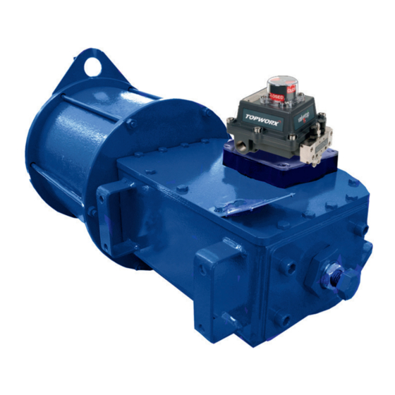
Biffi ALGA
Double-Acting Pneumatic Actuator
Copyright © Biffi. The information in this document is subject to change without notice. Updated data sheets can be obtained from our website www.biffi.it or from your nearest Biffi Center:
Biffi Italia s.r.l. - Strada Biffi 165, 29017 Fiorenzuola d'Arda (PC) – Italy PH: +39 0523 944 411 – biffi_italia@biffi.it
Installation, Operation and Maintenance Manual
MAN 564 Rev. 6
June 2020
Advertisement
Table of Contents
Troubleshooting

Related Manuals for BIFFI ALGA Series


Summary of Contents for BIFFI ALGA Series
- Page 1 Double-Acting Pneumatic Actuator Copyright © Biffi. The information in this document is subject to change without notice. Updated data sheets can be obtained from our website www.biffi.it or from your nearest Biffi Center: Biffi Italia s.r.l. - Strada Biffi 165, 29017 Fiorenzuola d'Arda (PC) – Italy PH: +39 0523 944 411 – biffi_italia@biffi.it...
- Page 2 Revision Details Installation, Operation and Maintenance Manual June 2020 MAN 564 Rev. 6 Revision Details Rev. Date Description Prepared Checked Approved June 2020 General update (Migration to new template) March 2018 Revised Data-plate Ermanni Orefici Vigliano April 2016 Updated Applicable Regulation (Section 1.1.1) Ermanni Orefici Vigliano...
-
Page 3: Table Of Contents
Residual risks .................... 27 Calibration of the Angular Stroke .............. 27 Calibration of Micro-switches ..............34 Calibration of the Operation Time (Biffi limit switch box only) ....34 Section 4: Operational Tests and Inspections Operational Tests and Inspections ................. 36... - Page 4 Table of Contents Installation, Operation and Maintenance Manual June 2020 MAN 564 Rev. 6 Section 5: Maintenance Periodic Maintenance ................37 5.1.1 Check and Restore Oil Level in the Hydraulic Manual Override..38 5.1.2 Gas Supply Dehydrating Filter Maintenance (If Foreseen) ....40 Extraordinary Maintenance ...............
-
Page 5: Section 1: General Warnings
Biffi Italia s.r.l. pays the highest attention to collecting and verifying the documentation contained in this user manual. However Biffi Italia s.r.l. is not liable for any mistakes contained in this manual, for damage or accidents due to the use of the latter. The information contained is of exclusive reserved ownership of Biffi Italia s.r.l. -
Page 6: Identification Plate
The actuator yoke has a hole with keyways suitable for the assembly of an insert bush the internal hole of which is machined (by Biffi or at Customer's care), according to the shape and dimensions of the valve stem. Biffi can supply different types of control system following Customer's requirements. -
Page 7: Data Sheet
Installation, Operation and Maintenance Manual Section 1: General Warnings MAN 564 Rev. 6 June 2020 Figure 2 Identification of actuator parts Manual handpump - MHP Control system (optional) (optional) Valve position indicator Pneumatic Scotch yoke mechanism Hydraulic cylinder for ALGA-MHP models cylinder or second pneumatic cylinder for ALGA*2 Valve coupling... -
Page 8: Section 2: Installation
Section 2: Installation Installation, Operation and Maintenance Manual June 2020 MAN 564 Rev. 6 Section 2: Installation Checks upon Actuator Receipt • Check that the model, the serial number of the actuator and the technical data reported on the identification plate correspond with those of order confirmation (Section 1.2). - Page 9 Installation, Operation and Maintenance Manual Section 2: Installation MAN 564 Rev. 6 June 2020 Figure 4 Lifting points for ALGA / ALGA-MHP / ALGA-MSJ actuators 1, 2 = Lifting points (obligatory) 3 = Balancing point Figure 5 Lifting points for ALGA / ALGA-MHP / ALGA-MSJ actuators 1 = Point of support 2 = Supports for lateral positioning 3 = Don’t lay the actuator on tie-rods of cylinder /s and don’t lay the actuator on...
- Page 10 BIFFI IS NOT LIABLE FOR ANY PERSONEL INJURY DUE TO INCORRECT USE REFFER TO IOM WARNING Any lifting method different from what described above is strictly forbidden. Biffi reject any responsibility for damages to goods or injuries to persons coming from wrong lifting operations. Installation...
-
Page 11: Storage
Types of Assembly For coupling to the valve, the housing is provided with a flange with threaded holes according to Biffi standard tables (SCN6200; SCN6200-1; SCN6201; SCN6201-1 SCN6201-3 SCN6201-5). The number, dimensions and diameter of the holes are made in accordance with ISO 5211, but for actuator models 0.3 to 6 the holes are drilled on the... - Page 12 Installation, Operation and Maintenance Manual June 2020 MAN 564 Rev. 6 The yoke has bored with keyways for coupling to the valve stem, the dimensions of which are according to Biffi standard tables SCN6200*- and SCN6201*: Figure 7 Drive sleeve N. threaded holes...
- Page 13 Installation, Operation and Maintenance Manual Section 2: Installation MAN 564 Rev. 6 June 2020 Figure 8 Drive sleeve N. threaded holes PCD, number and size according to ISO 5211 (but the holes are on centerline instead of straddle the centerline) Flow line Top view of the Scotch yoke mechanism (actuator shown in closed position)
- Page 14 Section 2: Installation Installation, Operation and Maintenance Manual June 2020 MAN 564 Rev. 6 Figure 9 Drive sleeve N. threaded holes PCD, holes, number and size according to ISO 5211 Flow line Top view of the Scotch yoke mechanism (actuator shown in closed position) Table 3.
- Page 15 Installation, Operation and Maintenance Manual Section 2: Installation MAN 564 Rev. 6 June 2020 Figure 10 Drive sleeve N. threaded holes PCD, holes, number and size according to ISO 5211 Flow line Top view of the Scotch yoke mechanism (actuator shown in closed position) Table 4.
- Page 16 Section 2: Installation Installation, Operation and Maintenance Manual June 2020 MAN 564 Rev. 6 Figure 11 Drive sleeve N. threaded holes Flow line Top view of the Scotch yoke mechanism (actuator shown in closed position) Table 5. Dimensions (mm) Actuator model ød1 ød2 ød3...
- Page 17 Installation, Operation and Maintenance Manual Section 2: Installation MAN 564 Rev. 6 June 2020 Figure 12 Drive sleeve N. threaded holes PCD, holes, number and size according to ISO 5211 Flow line Top view of the Scotch yoke mechanism (actuator shown in closed position) Table 6.
- Page 18 Section 2: Installation Installation, Operation and Maintenance Manual June 2020 MAN 564 Rev. 6 Figure 13 Drive sleeve N. threaded holes PCD, number and size according to ISO 5211 (but the holes are on centerline instead of straddle the centerline) Flow line Top view of the Scotch yoke mechanism (actuator shown in closed position)
- Page 19 Insert bush turned upside down The Biffi insert bush with 2 external keys at 45° allows to position the keyway for the valve every 90°. Consequently actuator can be mounted in 4 positions at 90° on top of the valve.
-
Page 20: Assembly Procedure
Section 2: Installation Installation, Operation and Maintenance Manual June 2020 MAN 564 Rev. 6 2.4.2 Assembly Procedure NOTICE Failure to comply with the following procedures may impair product warranty. WARNING Installation, commissioning and maintenance and repair works should be carried out by qualified staff. -
Page 21: Pneumatic Connections
Check the absence of leakages from pneumatic connections. NOTICE If necessary to mount components not in Biffi scope of supply, please check the accessories mounting hole details in the documents TN 1028 (for metric dimension) or TN 1028U (for imperial dimension). -
Page 22: Electrical Connections (If Any)
Section 2: Installation Installation, Operation and Maintenance Manual June 2020 MAN 564 Rev. 6 Electrical Connections (If Any) WARNING Use components appropriate as for type, material and dimensions. The connections should be made by qualified staff. Before carrying out any operation, cut line power off. Safety provisions: 2006/95/EC: Directive for low voltage equipment (until 19 April 2016) 2014/35/EU from 20 April 2016... -
Page 23: Commissioning
Installation, Operation and Maintenance Manual Section 2: Installation MAN 564 Rev. 6 June 2020 Commissioning WARNING Check that values of electrical supply to the control group (if foreseen) are compatible with those on the plate on the junction box (Figure 15). Installation, commissioning and maintenance and repair works should be made by qualified staff. -
Page 24: Section 3: Operation And Use
Section 3: Operation and Use Installation, Operation and Maintenance Manual June 2020 MAN 564 Rev. 6 Section 3: Operation and Use Operation Description In the normal operating situation, the ALGA actuator is fed by pressurized gas which flows into the relevant cylinder chamber (for example opening). The cylinder piston stroke causes the actuator operation and the consequent valve movement to the operational position requested (in this case to the “open”... - Page 25 Installation, Operation and Maintenance Manual Section 3: Operation and Use MAN 564 Rev. 6 June 2020 Figure 17 Table 10. Parts list Item Name Housing Yoke Yoke bushing Cover Guide block pin Sliding block Guide block Guide bar Guide block bushing Travel stop screw Cylinder head flange Piston rod bushing...
- Page 26 Section 3: Operation and Use Installation, Operation and Maintenance Manual June 2020 MAN 564 Rev. 6 For local or remote operations, please refer for information only to par. 3.3.1 , 3.3.2 , 3.3.3 and 3.3.4 and prior to technical documentation furnished with actuators. Typical schematics for various applications are follow attached for information only, the function described are fournished only on specific customer demand.
- Page 27 Installation, Operation and Maintenance Manual Section 3: Operation and Use MAN 564 Rev. 6 June 2020 Figure 19 ON-OFF service: air fail safe system Pressurized air Pressurized air (low pressure) Atmospheric pressure air The system allows 'fail safe' operation when the pressure in the gas supply line drops below a set value.
- Page 28 Section 3: Operation and Use Installation, Operation and Maintenance Manual June 2020 MAN 564 Rev. 6 Figure 20 Modulating service Electropneumatic positioner Electric control signal Pneumatic Pneumatic control signal positioner Pressurized air (supply) Reduced pressure air (opening chamber) Reduced pressure air (closing chamber) When modulating control is required as a function of a pneumatic or electric control signal, a positioned (5) is used, which controls the supply to the actuator cylinder to keep the valve in the required angular position.
- Page 29 Installation, Operation and Maintenance Manual Section 3: Operation and Use MAN 564 Rev. 6 June 2020 Figure 21 Emergencency manual override The MHW - MSJ jackscrew manual override can be supplied for model up to 3. The override is mounted on the left side of the actuator, the jackscrew end is screwed into the guide block.
- Page 30 Section 3: Operation and Use Installation, Operation and Maintenance Manual June 2020 MAN 564 Rev. 6 Figure 23 Pneumatic operation Manual operation The diagram is drawn with actuator under pneumatic The diagram is drawn with actuator under manual operation in opening. The flow regulator Fa allows control operation towards open.
-
Page 31: Residual Risks
Installation, Operation and Maintenance Manual Section 3: Operation and Use MAN 564 Rev. 6 June 2020 Residual risks WARNING It is recommended to pipe exhaust gas. The actuator has parts under pressure. Use the due caution. Use individual protections provided for by the laws and provisions in force. Calibration of the Angular Stroke The angular stroke of the yoke can be adjusted between 82°÷98°... - Page 32 Section 3: Operation and Use Installation, Operation and Maintenance Manual June 2020 MAN 564 Rev. 6 For the adjustment of the travel stop screws proceed as follows: Loosen the lock nut (2) with a proper wrench (c2). If the actuator angular stroke is stopped before reaching the end position (fully open or closed), unscrew the stop screw (1) by turning it anticlockwise with a proper wrench (c1), until the valve reaches the right position.
- Page 33 Installation, Operation and Maintenance Manual Section 3: Operation and Use MAN 564 Rev. 6 June 2020 Figure 27 Table 12. Pneumatic cylinder size Wrench c1 (mm) Wrench c2 (mm) 1000 1100 1200 1300 1450 For the adjustment of the mechanical stop srewed into the left side of housing, follow these steps (Figure 24 and 28): •...
- Page 34 Section 3: Operation and Use Installation, Operation and Maintenance Manual June 2020 MAN 564 Rev. 6 Figure 28 Mechanical stop on the housing Table 13. Actuator model Wrench c1 (mm) Wrench c2 (mm) Figure 29 Mechanical stop on the housing Table 14.
- Page 35 Installation, Operation and Maintenance Manual Section 3: Operation and Use MAN 564 Rev. 6 June 2020 Figure 30 Optional (if foreseen) For the adjustment of the mechanical stop screwed on the end flange of manual override (see Section 7.2 Figure 51: sectional drawing for manual jackscrew MSJ – MHW). Figure 31 Mechanical stop on the end flange of manual override Table 15.
- Page 36 Section 3: Operation and Use Installation, Operation and Maintenance Manual June 2020 MAN 564 Rev. 6 Figure 32 Mechanical stop on the end flange of manual override Table 16. Actuator model Wrench c1 (mm) Wrench c2 (mm) Figure 33 Optional (if foreseen) Operation and Use...
- Page 37 Installation, Operation and Maintenance Manual Section 3: Operation and Use MAN 564 Rev. 6 June 2020 For the adjustment of the mechanical stop on the end flange of hydraulic cylinder of MHP, follow these steps (Figure 34): • Remove with the specific wrench (c1) the plug (t). •...
-
Page 38: Calibration Of Micro-Switches
Calibration of the Operation Time (Biffi limit switch box only) The calibration of the operation time is made by Biffi Italia s.r.l. according to customer requirements and to technical data-sheet included in technical documentation. If necessary it’s possible to modify or reset the operating time through two flow regulation valves placed between the control valves enclosure and the pneumatic cylinder (Figure 35). - Page 39 Installation, Operation and Maintenance Manual Section 3: Operation and Use MAN 564 Rev. 6 June 2020 To carry out the adjustment, use an adequate Allen wrench and follow these steps (Figure 35): • Loosen the locknut. • Screw with a screwdriver the setting screw to increase the operation time. •...
-
Page 40: Section 4: Operational Tests And Inspections
Section 4: Operational Tests and Inspections Installation, Operation and Maintenance Manual June 2020 MAN 564 Rev. 6 Section 4: Operational Tests and Inspections NOTICE To ensure the guaranteed SIL grade, according to IEC 61508, the functionality of actuator must be checked with regular intervals of time, as described in the Safety Manual. Operational Tests and Inspections... -
Page 41: Section 5: Maintenance
Installation, Operation and Maintenance Manual Section 5: Maintenance MAN 564 Rev. 6 June 2020 Section 5: Maintenance NOTICE Before executing any maintenance operation, it is necessary to close the pneumatic supply line and discharge pressure from the cylinder of the actuator and from the control unit (if foreseen). -
Page 42: Check And Restore Oil Level In The Hydraulic Manual Override
Section 5: Maintenance Installation, Operation and Maintenance Manual June 2020 MAN 564 Rev. 6 Figure 37 Level measuring stick Maximum level Minimum level 5.1.1 Check and Restore Oil Level in the Hydraulic Manual Override Operate the distributor lever to “closing manual operation”. Figure 38 Move the actuator into his “fail to close”... - Page 43 NOTICE For refill use oil of the same brand as previous, refer to related technical documentation. Table 18. Features of hydraulic oil suggested by Biffi Italia s.r.l for refilling in different working condition: Standard temperature conditions (-30 °C/+85 °C) Producer...
-
Page 44: Gas Supply Dehydrating Filter Maintenance (If Foreseen)
Section 5: Maintenance Installation, Operation and Maintenance Manual June 2020 MAN 564 Rev. 6 5.1.2 Gas Supply Dehydrating Filter Maintenance (If Foreseen) The gas supply filter is fitted with a mechanical filter and a drain valve to discharge periodically the water generated by the condensation of the humidity inside the gas supply. NOTICE During the routine maintenance it is recommended to check and clean the mechanical filter and replace it in case of heavy dirty conditions. -
Page 45: Extraordinary Maintenance
Installation, Operation and Maintenance Manual Section 5: Maintenance MAN 564 Rev. 6 June 2020 Extraordinary Maintenance If there are leaks in the hydraulic cylinder, pneumatic cylinder or a malfunction in the mechanical components, or in case of scheduled preventive maintenance, the actuator must be dis-assembled and seals must be replaced with reference to the follow general sectional drawing and adopting the following procedures. - Page 46 Section 5: Maintenance Installation, Operation and Maintenance Manual June 2020 MAN 564 Rev. 6 WARNING Before executing any maintenance operation, it is necessary to intercept the supply line and discharge pressure from the cylinder of the actuator. If the actuator can be operated, it is essential to take it to fail safe position, otherwise the actuator should be disassembled from the valve and follow these steps: Remove the nuts (16) and the washers (24) from the tie rods (18) at the end flange (22) side.
- Page 47 Installation, Operation and Maintenance Manual Section 5: Maintenance MAN 564 Rev. 6 June 2020 Assemble the washer (44) onto the sealing washer (43). Screw the stop screw into the threaded hole of the end flange until it reaches its original position (the same protrusion with reference to the flange surface). Check that the sealing washer (43) and the washer (44) are in contact with the flange surface.
- Page 48 Section 5: Maintenance Installation, Operation and Maintenance Manual June 2020 MAN 564 Rev. 6 Figure 41 ALGA double acting pneumatic actuator Table 20. Parts list Item Description Item Description Cover Lifting eyelet Screw Spring washer Guide block pin Vent valve Stop setting screw Sliding block Screw...
- Page 49 Installation, Operation and Maintenance Manual Section 5: Maintenance MAN 564 Rev. 6 June 2020 Replacement of hydraulic cylinder seals (see Figure 41) only for ALGA-MHP hydraulic handpump manual override If there are leaks in the hydraulic cylinder or a malfunction in the mechanical components, or in case of scheduled preventive maintenance, the actuator must be dis-assembled and seals must be replaced with reference to the sectional drawing and adopting the following procedures:...
- Page 50 Section 5: Maintenance Installation, Operation and Maintenance Manual June 2020 MAN 564 Rev. 6 To replace the piston seal ring (9) and the O-ring (19) proceed as follows: Remove the existing Teflon seal ring (9) and the O-ring (19) from their groove. Clean the groove carefully and lubricate it with a protective oil film.
- Page 51 Installation, Operation and Maintenance Manual Section 5: Maintenance MAN 564 Rev. 6 June 2020 Reassemble Assemble the new gasket (item 36-Figure 41) after cleaning the surfaces of housing (item 8-Figure 41) and head flange (item 2) which are in contact. Assemble the head flange and tighten the screws (item 7-Figure 41) to the recommended torque.
- Page 52 Section 5: Maintenance Installation, Operation and Maintenance Manual June 2020 MAN 564 Rev. 6 Figure 42 Cylinder Table 21. Parts list Item Qty. Description Material Piston rod bushing Steel + Bronze + Teflon Head flange Carbon steel O-ring *NBR rubber Piston rod seal ring *Teflon + Graphite O-ring...
-
Page 53: Mhp Hydraulic Manual Override Maintenance And Troubleshooting
Installation, Operation and Maintenance Manual Section 5: Maintenance MAN 564 Rev. 6 June 2020 MHP Hydraulic Manual Override Maintenance and Troubleshooting 5.3.1 Operation (see the attached operating diagram MAN 562-A) The “MHP” hydraulic manual override and speed control unit is utilized, in connection with the actuator hydraulic cylinder, for the manual operation and for the speed control during the pneumatic operation of pneumatic double acting actuators. -
Page 54: Setting
Section 5: Maintenance Installation, Operation and Maintenance Manual June 2020 MAN 564 Rev. 6 Pneumatic closing operation The oil flows from the hydraulic cylinder chamber, head flange side, via the flow regulator (Fc), the valve (D) and the flow regulator (Fa), free flow direction, to the hydraulic cylinder chamber, rear flange side. - Page 55 B) Settings of relief valves (see the attached sectional drawings) The relief valve (item Ra of operating diagram MAN562-A) is set at Biffi factory at a proper value and there is no reason to change the setting on the field.
- Page 56 Section 5: Maintenance Installation, Operation and Maintenance Manual June 2020 MAN 564 Rev. 6 Figure 43 Hydraulic control unit Oil tank relief valve Relief valve for automatic operation Flow regulator Relief valve for manual operation Table 22. Parts list Item Qty.
-
Page 57: Lubrication Of Mechanism
For this operation it is necessary to disassemble the mechanism cover. In larger actuators the lubrication can be performed through the inspection holes of the cover after removing the plugs. The following grease is used by Biffi for standard working temperature and suggested for re-lubrication: Table 23. -
Page 58: Dismantling And Demolition
Section 5: Maintenance Installation, Operation and Maintenance Manual June 2020 MAN 564 Rev. 6 Dismantling and Demolition Before starting the disassembly a large area should be created around the actuator so to allow any kind of movement without problems of further risks created by worksite. WARNING Before disassembling the actuator it is necessary to close the pneumatic feed line and discharge pressure from the cylinder of the actuator, from the control unit and from the... -
Page 59: Section 6: Troubleshooting
Repair or replace Actuator does not work Wrong position of the distributor of Restore correct position the manual hydraulic group Call Biffi Italia s.r.l. Failure of the control group Customer Service Low supply pressure Restore (Section 1.4) Low supply pressure Restore (Section 1.4) -
Page 60: Section 7: Layouts
Section 7: Layouts Spare Parts Order For spare parts order to the relevant Biffi office please make reference to Biffi order confirmation concerning all the supply, and serial number of the actuator (Section 1.2) for any specific spare part for a specific actuator model. -
Page 61: Parts List For Maintenance And Replacing Procedure
** Cycles performed by actuator in a 25 years expected lifetime - the minimum performed cycles are guaranted by Biffi based on service conditions listed: All the valve required torques have to be lower than actuator max operating torque (MOT) The ratio between valve required running torque and actuator max operating torque (MOT) has to be >... - Page 62 ** Cycles performed by actuator in a 25 years expected lifetime - the minimum performed cycles are guaranted by Biffi based on service conditions listed: All the valve required torques have to be lower than actuator max operating torque (MOT).
- Page 63 Installation, Operation and Maintenance Manual Section 7: Layouts MAN 564 Rev. 6 June 2020 Figure 46 Pneumatic cylinder Table 27. Parts list Item Qty. Description Material Piston rod bushing Steel + Bronze + PTFE O-ring *NBR O-ring *NBR Head flange Carbon steel Carbon steel Tie rod...
- Page 64 Section 7: Layouts Installation, Operation and Maintenance Manual June 2020 MAN 564 Rev. 6 Figure 47 Hydraulic cylinder (optional: only for ALGA-MHP hydraulic handwheel manual override) Table 28. Parts list Item Qty. Description Material Piston rod bushing Steel + Bronze + PTFE Head flange Carbon steel O-ring...
- Page 65 Installation, Operation and Maintenance Manual Section 7: Layouts MAN 564 Rev. 6 June 2020 Figure 48 Assembly kit Table 29. Parts list Item Qty. Description Material Screw Alloy steel Gasket *Fiber Side plate Carbon steel Gasket *Fiber Washer Carbon steel Adaptor bush Alloy steel Washer...
- Page 66 Section 7: Layouts Installation, Operation and Maintenance Manual June 2020 MAN 564 Rev. 6 Figure 49 Hydraulic control unit MHP Oil tank relief valve Relief valve for automatic operation Flow regulator Relief valve for manual operation Table 30. Parts list Item Qty.
- Page 67 Installation, Operation and Maintenance Manual Section 7: Layouts MAN 564 Rev. 6 June 2020 Figure 50 Handpump Table 31. Parts list Item Description Material Ball Stainless steel Delivery valve bush Carbon steel Suction valve bush Carbon steel Spring Stainless steel Suction valve ring Carbon steel Spring retainer ring...
- Page 68 Section 7: Layouts Installation, Operation and Maintenance Manual June 2020 MAN 564 Rev. 6 Figure 51 Jackscrew manual override MSJ or MHW ENGAGED TO OPEN TO CLOSE DISENGAGED Table 32. Parts list Item Description Material Item Qty. Description Material Protection pipe Carbon steel Screw Carbon steel...
-
Page 69: Section 8: Date Report For Maintenance Operations
Installation, Operation and Maintenance Manual Section 8: Date Report for Maintenance Operations MAN 564 Rev. 6 June 2020 Section 8: Date Report for Maintenance Operations Last maintenance operation date: (in factory, on delivery): ……… exec. by : ………… ……… exec. by : ………… ………... - Page 70 VCIOM-03129-EN ©2020 Biffi. All rights reserved. Biffi Italia s.r.l. Strada Biffi 165 The contents of this publication are presented for information purposes only, 29017 Fiorenzuola d’Arda (PC) and while every effort has been made to ensure their accuracy, they are not...
Need help?
Do you have a question about the ALGA Series and is the answer not in the manual?
Questions and answers