BIFFI RPS Installation, Operation And Maintenance Manual
Spring-return pneumatic actuator
Hide thumbs
Also See for RPS:
- Installation, operation and maintenance manual (21 pages) ,
- Use and maintenance manual (41 pages) ,
- Installation, operation and maintenance manual (40 pages)
Table of Contents
Advertisement
Quick Links
Installation, Operation and Maintenance Manual
MAN 573-C Rev. 2
August 2024
Biffi RPS
Spring-Return Pneumatic Actuator
Copyright © Biffi. The information in this document is subject to change without notice. Updated installation, operation and maintenance manuals can be obtained from our website
www.biffi.it or from your nearest Biffi Center: Biffi Italia s.r.l. - Strada Biffi 165, 29017 Fiorenzuola d'Arda (PC) – Italy PH: +39 0523 944 411 – biffi_italia@biffi.it
Advertisement
Table of Contents

Related Manuals for BIFFI RPS


Summary of Contents for BIFFI RPS
- Page 1 Copyright © Biffi. The information in this document is subject to change without notice. Updated installation, operation and maintenance manuals can be obtained from our website www.biffi.it or from your nearest Biffi Center: Biffi Italia s.r.l. - Strada Biffi 165, 29017 Fiorenzuola d'Arda (PC) – Italy PH: +39 0523 944 411 – biffi_italia@biffi.it...
- Page 2 Notes Installation, Operation and Maintenance Manual August 2024 MAN 573-C Rev. 2 This page is intentionally left blank.
-
Page 3: Table Of Contents
Installation, Operation and Maintenance Manual Table of Contents MAN 573-C Rev. 2 August 2024 Table of Contents Section 1: General Warnings Generalities ....................... 1 1.1.1 Applicable Regulation ................. 1 1.1.2 Terms and Conditions ................. 1 1.1.3 Electrostatic Charge ..................1 Identification Plate .................... - Page 4 Table of Contents Installation, Operation and Maintenance Manual August 2024 MAN 573-C Rev. 2 Section 6: Troubleshooting Failure or Breakdown Research ................29 Procedure for Adjustment of Thrust Bearing-Screw ........29 Section 7: Spare Parts Spare Parts Order ....................30 Parts List for Maintenance and Replacement Procedure ......31 Section 8: Date Report for Maintenance Operations Date Report for Maintenance Operations ..............33 Table of Contents...
-
Page 5: Section 1: General Warnings
Installation, Operation and Maintenance (IOM) manual. However, Biffi Italia s.r.l. is not liable for any mistakes contained in this manual, for damage or accidents due to the use of the latter. The information contained is of exclusive reserved ownership of Biffi Italia s.r.l. -
Page 6: Identification Plate
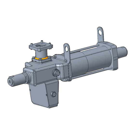
Charging Hazard See Instructions Introducing the Actuator RPS actuators are pneumatic low-pressure spring-return, suitable for any quarter-turn application such as ball, plug, butterfly valves or dampers, in both on/off and modulating heavy-duty service. The actuator is made up of a rack and pinion mechanism, which transforms the linear movement of the pneumatic cylinder, in one direction, and of the spring, in the opposite direction, into the rotary movement for the valve operation. - Page 7 Installation, Operation and Maintenance Manual Section 1: General Warnings MAN 573-C Rev. 2 August 2024 Figure 2. RPS Pneumatic Actuator Mounting Dimensions - Couplings VIEW FROM X VIEW FROM Y ØE ØF ØC ØC №4 THREADED HOLES №4 THREADED HOLES ØH...
- Page 8 Section 1: General Warnings Installation, Operation and Maintenance Manual August 2024 MAN 573-C Rev. 2 Figure 3. RPS Pneumatic Actuator Mounting Dimensions - Accessories FRONT SIDE ±0.2 ØE №4 THREADED HOLES TOP VIEW BACK SIDE ±0.2 ØE №4 THREADED HOLES (OPTIONAL) Table 2.
-
Page 9: Data Sheet
Installation, Operation and Maintenance Manual Section 1: General Warnings MAN 573-C Rev. 2 August 2024 Data Sheet Supply fluid: Air, Nitrogen or sweet gas Operating temperature: Standard: from -30 to +100 °C Optional: from -60 to +140 °C Design pressure: 12 bar maximum Supply pressure: Please refer to technical document “actuator data sheet”... -
Page 10: Section 2: Installation
Section 2: Installation Installation, Operation and Maintenance Manual August 2024 MAN 573-C Rev. 2 Section 2: Installation Checks Upon Actuator Receipt • Check that the model, the serial number of the actuator and the technical data reported on the identification plate correspond with those of order confirmation (Section 1.2). - Page 11 Valve stem with horizontal axis: The actuator can also be lifted to assemble directly onto the valve with stem with horizontal axis. To make this operation easier, Biffi suggest moving the lifting eyelet from its standard position, and place it in this suggested position: Figure 5.
-
Page 12: Storage
LIFTING EYELET RACK AND PINION When it is necessary to lift the actuator in order to stabilize the RPS actuator during the transport in horizontal position, it is recommended to fix the actuator by the “stabilizing eyelets” placed on the top of the control cabinet. -
Page 13: Actuator Assembly On The Valve
NOTICE Fix the actuator to the valve flange using the stud bolts and nuts supplied by Biffi. In case the actuator is supplied without stud bolts and nuts, the following materials must be used as a minimum: •... - Page 14 Section 2: Installation Installation, Operation and Maintenance Manual August 2024 MAN 573-C Rev. 2 Figure 8. “RP” Pneumatic Actuators Coupling Dimensions VIEW FROM X VIEW FROM Y ØE ØF ØC ØC №4 THREADED HOLES №4 THREADED HOLES ØH THREADED HOLE ØN ØM THREADED HOLE ØN Table 3.
-
Page 15: Assembly Procedure
Installation, Operation and Maintenance Manual Section 2: Installation MAN 573-C Rev. 2 August 2024 2.4.2 Assembly Procedure NOTICE Failure to comply with the following procedures may void product warranty. WARNING Installation, commissioning and maintenance and repair works should be carried out by qualified staff. -
Page 16: Pneumatic Connections
Section 2: Installation Installation, Operation and Maintenance Manual August 2024 MAN 573-C Rev. 2 Pneumatic Connections Connect the actuator to the pneumatic feed line with fittings and pipes in accordance to the plant specifications. They must be sized correctly in order to guarantee the necessary air flow for the operation of the actuator, with pressure drops not exceeding the maximum allowable value. -
Page 17: Commissioning
Any calibration relative to the functional aspects of the actuator are preset at the factory, except the angular stroke setting because for this setting operation, the actuator must be placed on to the valve (see Section 3.4). Before any modifications, please contact Biffi Italia s.r.l. Upon actuator commissioning, please carry out the following checks: •... -
Page 18: Section 3: Operation And Use
Figure 9. RPS Cut Away For local or remote operations related to the actuator, please refer to technical documentation furnished with actuators. - Page 19 Installation, Operation and Maintenance Manual Section 3: Operation and Use MAN 573-C Rev. 2 August 2024 On/Off Service: Quick Spring Operation When fast action is required under spring operation, a quick exhaust valve (3) is installed in the cylinder directly port to exhaust the gas from the cylinder directly to the atmosphere. When the control valve (2) opens to the atmosphere a differential pressure is created across the quick exhaust valve (3) causing it to open.
-
Page 20: Residual Risks
The operations are carried out sending the proper signal through the control system in compliance with customer specifications. Please refer to applicable “operating diagram” and to Biffi technical documentation supplied. Calibration of the Angular Stroke It is important that the mechanical stops of the actuator (and not those of the valve) stop the angular stroke at both extreme valve position (fully open and fully closed), except when this is required by the valve operation (e.g., metal seated butterfly valves). - Page 21 Installation, Operation and Maintenance Manual Section 3: Operation and Use MAN 573-C Rev. 2 August 2024 Table 6. RP Travel Stop Screw Calibration Allen Key C3 Allen Key C1 (mm) Actuator Model Allen Key C3 (mm) Plug+FKM gasket RP 14/15 12 (plug 3/4 in.
-
Page 22: Calibration Of Microswitches
Section 3: Operation and Use Installation, Operation and Maintenance Manual August 2024 MAN 573-C Rev. 2 Calibration of Microswitches Refer to Safety Instructions Manual for limit switch box. NOTICE Operate only the microswitch corresponding to the direction of operation being carried out, as clearly reported on the microswitch. - Page 23 Installation, Operation and Maintenance Manual Section 3: Operation and Use MAN 573-C Rev. 2 August 2024 Figure 16. Cam Adjustment If the index (Figure 17), does not signal the proper position of the valve but is turned by 90°: • Remove the roll pin placed on the position indicator (index).
-
Page 24: Calibration Of The Operation Time
MAN 573-C Rev. 2 Calibration of the Operation Time The calibration of the operation time is made by Biffi Italia s.r.l. according to customer requirements and to technical data sheet included in technical documentation. If necessary, it is possible to modify or reset the operating time through the flow regulator valve placed on inlet of pneumatic supply (Figure 18). -
Page 25: Section 4: Operational Tests And Inspections
Installation, Operation and Maintenance Manual Section 4: Operational Tests and Inspections MAN 573-C Rev. 2 August 2024 Section 4: Operational Tests and Inspections NOTICE To ensure the guaranteed SIL grade, according to IEC 61508, the functionality of actuator must be checked with regular intervals of time, as described in the Safety Manual. Operational Tests and Inspections... -
Page 26: Section 5: Maintenance
Installation, commissioning and maintenance, and repair works should be carried out by qualified staff. Please refer to warning in Section 1. Periodic Maintenance RPS actuators are designed to operate long-term in heavy-duty operating conditions, without maintenance needs. NOTICE Periodicity and regularity of inspections is particularly influenced by specific environmental and working conditions. -
Page 27: Extraordinary Maintenance
Installation, Operation and Maintenance Manual Section 5: Maintenance MAN 573-C Rev. 2 August 2024 Extraordinary Maintenance If there are leaks in the pneumatic cylinder or a malfunction in the mechanical components, or in case of scheduled preventive maintenance, the actuator must be disassembled and seals must be replaced with reference to the general sectional drawing and adopting the following procedures. -
Page 28: Reassemble
Installation, Operation and Maintenance Manual Section 5: Maintenance August 2024 MAN 573-C Rev. 2 5.2.3 Reassemble Assemble the new cylinder gasket (7) on its seat on the end flange (4). Carefully clean the inside of the tube (13) and check that the entire surface, particularly that of the bevels, is not damaged. - Page 29 Installation, Operation and Maintenance Manual Section 5: Maintenance MAN 573-C Rev. 2 August 2024 Figure 19. RPS Spring-Return Pneumatic Actuator Assembly Drawing 22 12 16 13 3 30 17 10 28 2 31 36 14 10 17 Table 7. Parts List...
-
Page 30: Lubrication Of Mechanism
Installation, Operation and Maintenance Manual Section 5: Maintenance August 2024 MAN 573-C Rev. 2 Lubrication of Mechanism For normal duty, the rack and pinion mechanism of the actuator is lubricated “for life”. In case of high load and high frequency of operation, it may be necessary to periodically restore lubrication: it is advisable to apply a generous coating of grease on the contact surfaces of moving parts, especially on the surface of the rack in contact with the thrust bearing sliding block and on the teeth of the rack and pinion. - Page 31 If the service is not special (i.e., oxygen, hydrogen or other mentioned during the offer stage). Use an equivalent or better product in compliance with the grease proposed in the actual scope of supply by Biffi Fiorenzuola. Your grease supplier can verify and propose an alternative product at your responsibility. Maintenance...
-
Page 32: Dismantling And Tear Down
Installation, Operation and Maintenance Manual Section 5: Maintenance August 2024 MAN 573-C Rev. 2 Dismantling and Tear Down WARNING Before starting the disassembly, a large area should be created around the actuator to allow any kind of movement without problems of further risks created by work site. Before disassembling the actuator, it is necessary to close the pneumatic feed line and discharge pressure from the cylinder of the actuator, from the control unit and from the accumulator tank, if present. -
Page 33: Section 6: Troubleshooting
See Figure 20 and Section 6.2 bearing-screw torque value Figure 20. RPS Actuator Cutaway View with Thrust Bearing Screw RESTORE THE CORRECT POSITION OF THRUST BEARING SCREW Procedure for Adjustment of Thrust Bearing-Screw Please refer to Figure 19 and Section 5.2.1. -
Page 34: Section 7: Spare Parts
Section 7: Spare Parts Spare Parts Order For spare parts orders to the relevant Biffi office, please make reference to Biffi order confirmation concerning all the supply, and serial number of the actuator (Section 1.2) for any specific spare part for a specific actuator model. -
Page 35: Parts List For Maintenance And Replacement Procedure
Installation, Operation and Maintenance Manual Section 7: Spare Parts MAN 573-C Rev. 2 August 2024 Parts List for Maintenance and Replacement Procedure Figure 21. Rack and Pinion Mechanism - RPS Spring-Return Pneumatic Actuator Spare Parts... - Page 36 Section 7: Spare Parts Installation, Operation and Maintenance Manual August 2024 MAN 573-C Rev. 2 Table 9. Parts List Item Quantity Description Material Housing Nodular cast iron Pinion Nodular cast iron Piston Carbon steel End flange Carbon steel Rack Nodular cast iron Rack Nickel plated alloy steel Cylinder gasket...
-
Page 37: Date Report For Maintenance Operations
Installation, Operation and Maintenance Manual Section 8: Maintenance Operations MAN 573-C Rev. 2 August 2024 Section 8: Date Report for Maintenance Operations Last maintenance operation date: (in factory, on delivery ): ..exec. by: ......exec. by: ....... exec. by: ....Next maintenance operation date: ..exec. - Page 38 VCIOM-16742-EN © 2019, 2024 Biffi. All rights reserved. Biffi Italia s.r.l. Strada Biffi 165 The contents of this publication are presented for informational purposes 29017 Fiorenzuola d’Arda (PC) only, and while every effort has been made to ensure their accuracy,...
Need help?
Do you have a question about the RPS and is the answer not in the manual?
Questions and answers