
Related Manuals for SST Automation SSTCOMM GT200-DP-RS


Summary of Contents for SST Automation SSTCOMM GT200-DP-RS
- Page 1 Universal Serial / PROFIBUS DP Gateway GT200-DP-RS User Manual V6.1 Rev A SST Automation E-mail: SUPPORT@SSTCOMM.COM WWW.SSTCOMM.COM...
- Page 2 The product has many applications. The users must make sure that all operations and results are in accordance with the safety of relevant fields, and the safety includes laws, rules, codes and standards. Copyright Copyright © 2021 by SST Automation. All rights reserved. Trademark is the registered trade mark of SST Automation.
-
Page 3: Table Of Contents
GT200-DP-RS Universal Serial/PROFIBUS DP Gateway User Manual Catalog 1 Product Overview..............................1 1.1 Product Function.............................1 1.2 Product Features............................. 1 1.3 Technical Specifications..........................1 1.4 Revision History............................. 3 2 Hardware Descriptions.............................. 4 2.1 Product Appearance............................4 2.2 Indicators.................................4 2.3 LED Display..............................5 2.4 DP Address and Mode Setting Button...................... - Page 4 GT200-DP-RS Universal Serial/PROFIBUS DP Gateway User Manual 6.4.1 Interface of Fieldbus Configuration View..................29 6.4.2 Interface of Subnet Configuration View....................30 6.4.3 Interface of Node Configuration View....................35 6.4.4 Interface of Command Configuration View..................35 6.5 Conflict Detection............................37 6.5.1 Operation of Command List......................37 6.5.2 Operation of Memory Mapping Area....................
-
Page 5: Product Overview
GT200-DP-RS Universal Serial/PROFIBUS DP Gateway User Manual 1 Product Overview 1.1 Product Function The GT200-DP-RS gateway enables data to establish communication between the Modbus or universal serial devices with RS-485/RS-232/RS-422 interface and PROFIBUS DP master such as Siemens PLC. It also supports data/status monitoring and debugging. - Page 6 GT200-DP-RS Universal Serial/PROFIBUS DP Gateway User Manual 4800, 9600, 19.2 K, 38.4K, 57.6K and 115.2K bps. Parity: None, Odd, Even, Mark and Space. [4] As a Modbus master, supports 01, 02, 03, 04, 05, 06, 15 and 16 function codes. ...
-
Page 7: Revision History
GT200-DP-RS Universal Serial/PROFIBUS DP Gateway User Manual 1.4 Revision History Revision Date Chapter Description V6.1 08/11/2020 New Release V6.1, Rev A 08/20/2021 Revised technical details. New quick start guide and chapters. revised. WWW.SSTCOMM.COM... -
Page 8: Hardware Descriptions
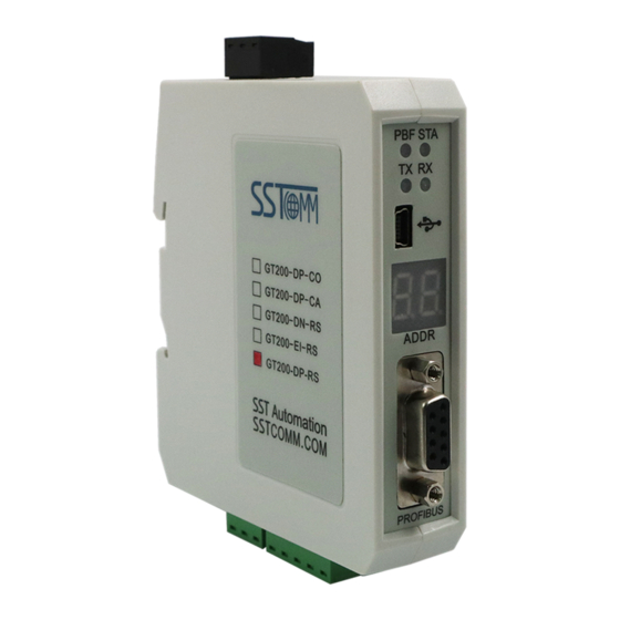
GT200-DP-RS Universal Serial/PROFIBUS DP Gateway User Manual 2 Hardware Descriptions 2.1 Product Appearance PROFIBUS DP Address Setting Button Power Interface Indicators USB Interface LED Display PRODIBUS DP Interface RS-232 Interface RS-485/422 Interface Note: This picture is for reference only. The product appearance is subject to the actual product. 2.2 Indicators Indicators State... -
Page 9: Led Display
GT200-DP-RS Universal Serial/PROFIBUS DP Gateway User Manual 2.3 LED Display The LED display is located in the front of the product. Please refer to chapter 2.4 to change DP address and operating mode. LED Display Description Configuration mode. Debug mode. Run mode. -
Page 10: Interface
GT200-DP-RS Universal Serial/PROFIBUS DP Gateway User Manual 2.5 Interface 2.5.1 Power Interface Description Not connected 24V DC + 24V+ 2.5.2 PROFIBUS DP Interface GND (Pin 5) PROFI_A (Pin 8) PROFI_B (Pin 3) PROFIBUS DP interface uses DB9 male-connector, and the pins are defined as follow: Description PROFI_B, Data+ RTS (Request to send) -
Page 11: Rs-485/Rs-422 Interface
GT200-DP-RS Universal Serial/PROFIBUS DP Gateway User Manual 2.5.3 RS-485/RS-422 Interface Description R-, RS-422 Receive- R+, RS-422 Receive+ D-, RS-485/RS-422 Transmit- D+, RS-485/RS-422Transmit+ 2.5.4 RS-232 Interface Description TX, connected to user’s device RS-232 RX RX, connected to user’s device RS-232 TX GND, connected to user’s device RS-232 GND WWW.SSTCOMM.COM... -
Page 12: Hardware Installation
GT200-DP-RS Universal Serial/PROFIBUS DP Gateway User Manual 3 Hardware Installation 3.1 Machine Dimension Size: 1.6 in * 5.0 in * 4.4 in / (40mm * 125mm * 110mm) 3.2 Installation Method Using 1.38 in (35mm) DIN RAIL. WWW.SSTCOMM.COM... -
Page 13: Quick Start Guide
GT200-DP-RS Universal Serial/PROFIBUS DP Gateway User Manual 4 Quick Start Guide 4.1 Connection Connect to the power supply. 24V+ 24V+ DC power: +24V Power interface of gateway Connect to the computer. You can use USB or RS-232 interface to configure the GT200-DP-RS. If you use the RS-232 interface, the connections is shown below: RS-232 Interface of Computer RS-232 Interface of GT200-DP-RS... - Page 14 GT200-DP-RS Universal Serial/PROFIBUS DP Gateway User Manual 485+ 485- RS-485 Device 1 485+ 485- RS-485 Interface of GT200-DP-RS RS-485 Device 2 485+ 485- RS-485 Device N The GT200-DP-RS supports RS-422 interface as well. RS-422 R- RS-422 R+ RS-422 D+ RS-422 D+ RS-422 Device 1 RS-422 D+ RS-422 Interface of GT200-DP-RS...
-
Page 15: Configuration
GT200-DP-RS Universal Serial/PROFIBUS DP Gateway User Manual 4.2 Configuration GT200-DP-RS V6.1 and higher versions support two configuration modes: DP Integrated Configuration mode and Software Configuration mode. The Software Configuration mode allows user to configure the GT200-DP-RS in SST-MPG-CFG software. The DP Integrated Configuration mode allows user to configure all parameters of the GT200-DP-RS in PROFIBUS integrated configuration software, such as STEP7 or TIA Portal. - Page 16 GT200-DP-RS Universal Serial/PROFIBUS DP Gateway User Manual Click “Subnet” located in the Equipment Section. Configure the parameters located in the Configuration Section to meet the needs of your project. Note: These parameters must match project device settings to ensure communication through our gateway. Right Click “Subnet”...
- Page 17 GT200-DP-RS Universal Serial/PROFIBUS DP Gateway User Manual Click the Command you wish to configure and configure the parameters in the Configuration Section to meet the needs of your project. Once the “Fieldbus”, “Subnet”, Node(s), and Command(s) are configured, click “AutoMap” icon on the toolbar to map the Modbus data to the PROFIBUS DP network.
-
Page 18: Configure By Step7 (Profibus Integrated Configuration Software)
GT200-DP-RS Universal Serial/PROFIBUS DP Gateway User Manual Note: The GT200-DP-RS will apply the new configuration after entering Run mode. After downloading, the software will ask to switch mode. You can also switch mode manually by setting button, referring to chapter 2.4. - Page 19 GT200-DP-RS Universal Serial/PROFIBUS DP Gateway User Manual The installed GSD files are in the corresponding folder. Add the GT200-DP-RS to the PROFIBUS DP bus. Drag the device and modules in the catalog to the DP bus, as shown below. Note: In the “DP Integrated Configuration”...
- Page 20 GT200-DP-RS Universal Serial/PROFIBUS DP Gateway User Manual The following steps introduce how to configure the GT200-DP-RS as a Modbus Master. The device is “GT200-DP-RS Modbus Master V6.0”. (1) Double click on a GT200-DP-RS device to open its properties window. In “General” window, Set the DP parameters.
- Page 21 GT200-DP-RS Universal Serial/PROFIBUS DP Gateway User Manual After you finish the DP slave configuration, click “OK”. (2) Add modules to the device. Select the GT200-DP-RS device on the DP bus, then double click on the modules you want to add to in the catalog.
- Page 22 GT200-DP-RS Universal Serial/PROFIBUS DP Gateway User Manual Then set the Modbus parameters in the “Parameter Assignment” window, referring to the Modbus function code specifications. After you finish the configuration, click “OK”. Compile and download the configuration to the PROFIBUS DP PLC. WWW.SSTCOMM.COM...
-
Page 23: Debug
GT200-DP-RS Universal Serial/PROFIBUS DP Gateway User Manual 4.3 Debug The SST-MPG-CFG software provides debug function that allows user quickly monitor data communication through GT200-DP-RS. For more details, please refer to chapter 6.9. Note: Under “Software Configuration” mode (LED displays “-U”), the GT200-DP-RS supports debugging without DP master. -
Page 24: Working Principle
GT200-DP-RS Universal Serial/PROFIBUS DP Gateway User Manual 5 Working Principle The GT200-DP-RS has an input buffer and an output buffer. The data transmission between serial devices and PROFIBUS DP master through GT200-DP-RS is established by mapping address. 5.1 As Modbus Master When the serial interface of the GT200-DP-RS is configured as Modbus master: The data read from Modbus slave devices by function code 01, 02, 03 or 04 is stored in the input buffer then transmitted to PROFIBUS DP master. - Page 25 GT200-DP-RS Universal Serial/PROFIBUS DP Gateway User Manual The output buffer can be regarded as Input Status (1x) area and Input Register (4x) area for the Modbus master. The data of the output area can be read by function code 02 or 04. The PROFIBUS DP master writes the data to the output buffer.
-
Page 26: Universal Mode
GT200-DP-RS Universal Serial/PROFIBUS DP Gateway User Manual 5.3 Universal Mode 5.3.1 Data Exchange The GT200-DP-RS supports universal serial protocol that allows PROFIBUS DP master to communicate with user’s serial devices of customized protocol. PROFIBUS DP Master PROFIBUS input data PROFIBUS output data Ei j D1 D2 …... - Page 27 GT200-DP-RS Universal Serial/PROFIBUS DP Gateway User Manual “00” to fill empty bytes: The M bytes of “00” are used to fill the empty if the output data is shorter then the PROFIBUS DP module length (for example, when sending only 4 bytes with an 8-byte output module, the left (8-4) bytes are filled with “00”).
-
Page 28: Data Mapping In Software Configuration Mode
GT200-DP-RS Universal Serial/PROFIBUS DP Gateway User Manual 5.4 Data Mapping in Software Configuration Mode In the “Software Configuration” mode, the data mapping address can be manually configured. The data mapping relationship between GT200-DP-RS buffer and PROFIBUS DP is shown below. The address N and M (or X and Y) can be discontinuous number. -
Page 29: Sst-Mpg-Cfg Software Instructions
GT200-DP-RS Universal Serial/PROFIBUS DP Gateway User Manual 6 SST-MPG-CFG Software Instructions The SST-MPG-CFG Software is of version 1.3.3. 6.1 Notes before Configuring SST-MPG-CFG is a product based on the Windows platform, and it can set related parameters and commands of Modbus and PROFIBUS DP through the GT200-DP-RS. - Page 30 GT200-DP-RS Universal Serial/PROFIBUS DP Gateway User Manual Note: All the gray parts in the software cannot be modified. Toolbar is shown as below: New: Create a new configuration project Save: Save the current configuration Open: Open a configuration project Add Nodes: Add a Modbus slave node WWW.SSTCOMM.COM...
- Page 31 GT200-DP-RS Universal Serial/PROFIBUS DP Gateway User Manual Delete Nodes: Delete a Modbus slave node Add Commands: Add a Modbus command Delete Commands: Delete a Modbus command Upload Configuration: Read the configuration from the module and show it in the software Download Configuration: Download the configuration from the software to the module Calculate Mapping Address: Calculating mapping address automatically Conflict Detection: Detect whether there is conflict in memory data buffer of the gateway...
-
Page 32: The Operation Of Equipment View
GT200-DP-RS Universal Serial/PROFIBUS DP Gateway User Manual 6.3 The Operation of Equipment View 6.3.1 Equipment View Interface 6.3.2 Operation Mode of Equipment View The equipment view supports three types of operation: Edit Menu, Edit Toolbar or Right click edit Menu. 6.3.3 Operation Types of Equipment View Add nodes: Right click on subnet or existing nodes, and then perform the operation of adding a new node. -
Page 33: The Operation Of Configuration View
GT200-DP-RS Universal Serial/PROFIBUS DP Gateway User Manual Delete commands: Right-click on the command and then perform the operation of deleting the command. Rename nodes: Left click on the node to be renamed, and then the edit status will be shown and you can rename it. -
Page 34: Interface Of Subnet Configuration View
GT200-DP-RS Universal Serial/PROFIBUS DP Gateway User Manual Size of PROFIBUS DP Input buffer: Set in PROFIBUS DP master configuration software, cannot be modified. Size of PROFIBUS DP Input buffer: Set in PROFIBUS DP master configuration software, cannot be modified. How to action after N successive response timeout: Clear data or Hold data can be selected. Successive response timeout for N times: 2 to 254 can be selected. - Page 35 GT200-DP-RS Universal Serial/PROFIBUS DP Gateway User Manual Baud Rate: 300, 600, 1200, 2400, 4800, 9600, 19200, 38400, 57600 and 115200bps optional Data bits: 8 Check Bit: none, odd, even, mark and space optional Stop bits: 1, 2 Transmission mode: RTU, ASCII optional Response timeout: When the Modbus master sends commands, the time waiting for a response from the slave ranges from 5~60000ms.
- Page 36 GT200-DP-RS Universal Serial/PROFIBUS DP Gateway User Manual Scan rate: Ratio of slow scan and fast scan. If the fast scan command sends 10 times, slow scan command sends 1 time. Status of Modbus Command Response: disable, 1byte, 2bytes, 3bytes, 4bytes, 5bytes, 6bytes, 7bytes, 8bytes, 9bytes, 10bytes, 11bytes, 12bytes and 13bytes can be selected.
- Page 37 GT200-DP-RS Universal Serial/PROFIBUS DP Gateway User Manual Baud Rate: 300, 600, 1200, 2400,4800, 9600, 19200, 38400, 57600 and 115200bps optional. Data Bits: 8 Check Bit: none, odd, even, mark and space optional Stop Bits: 1, 2 Slave Address: range is 0~247. Transmission Mode: RTU, ASCII Communication Interface: There are RS-232 and RS-485 to be selected.
- Page 38 GT200-DP-RS Universal Serial/PROFIBUS DP Gateway User Manual Choosing User Config in protocol type Configurable parameters are shown as follows: Baud Rate, Data Bits, Check Bit, Stop Bits, Frame Type, Time interval between Characters, Frame Length, Enable Auto Sending, Period of Auto Sending, Enable CRC Check, Communication Interface, Time interval between Character (Sending) and Time interval between Character (Receiving).
-
Page 39: Interface Of Node Configuration View
GT200-DP-RS Universal Serial/PROFIBUS DP Gateway User Manual Enable Auto Sending is Enabled Enable CRC Check: Enable, Disable optional Communication Interface: RS-232, RS-485 optional. (Note: If using the RS-422, here select RS-485) Time interval between Characters (Sending): The serial port of the GT200-DP-RS will send every byte according to the time interval. - Page 40 GT200-DP-RS Universal Serial/PROFIBUS DP Gateway User Manual Configurable parameters are shown as follows: Starting Address, Number of Data, Mapping Address (HEX), Mapping Bit (0~7) and Type of Scan Starting Address: The starting address of register or switching value or loop and so on in Modbus slave and the range is 0~65535.
-
Page 41: Conflict Detection
GT200-DP-RS Universal Serial/PROFIBUS DP Gateway User Manual 6.5 Conflict Detection For the detection of whether there exists conflict of "the starting address of memory mapping". 6.5.1 Operation of Command List All the configuration commands can be shown at the command list. Each select box before the command is used for checking the memory-mapping location of that command. -
Page 42: Hardware Communication
GT200-DP-RS Universal Serial/PROFIBUS DP Gateway User Manual 6.6 Hardware Communication Hardware communications' menu items are shown as follow: WWW.SSTCOMM.COM... -
Page 43: Serial Configuration
GT200-DP-RS Universal Serial/PROFIBUS DP Gateway User Manual 6.6.1 Serial Configuration The software automatically scans the available serial port of the system, and the available serial can be shown in the serial list. After modifying all the items, press "OK" to save your settings. 6.6.2 Upload Configuration Choose upload configuration, upload the gateway configuration information from the device to the software, the display interface is shown as follows:... -
Page 44: Download Configuration
GT200-DP-RS Universal Serial/PROFIBUS DP Gateway User Manual 6.6.3 Download Configuration Choose download configuration, download the reconfigured gateway information to the gateway, the display interface is shown as follows: Note: 1. Before downloading the configuration, please check whether the "serial port configuration" is the available port. -
Page 45: Save Configuration Project
GT200-DP-RS Universal Serial/PROFIBUS DP Gateway User Manual 6.7.2 Save Configuration Project Choosing "Save" can open a saved project before. 6.8 Export EXCEL The Excel document helps users to examine the configuration. 6.9 Debug This function is for debugging Modbus network communications, the interface is shown as follows: Click the Debug button will show up the firmware select dialog box, choose the matched version: Note: Make sure to set the gateway to debug mode. -
Page 46: Debug Interface Of 4.X Or 3.X
GT200-DP-RS Universal Serial/PROFIBUS DP Gateway User Manual 6.9.1 Debug Interface of 4.X or 3.X Firmware Version of 4.X or 3.X only supports debug function in the protocol of "Modbus Master" Status: Shows communication state with slave: response ok, response timeout, response abnormal and response error Slave Address: Slave address in the configuration file (HEX) Starting Address: "Modbus register starting address"... -
Page 47: Debug Interface Of 5.X And Above
GT200-DP-RS Universal Serial/PROFIBUS DP Gateway User Manual Data: Data writing into the gateway 6.9.2 Debug Interface of 5.x and above Status: Shows communication state with slave: respond correctly, response timeout, respond abnormally and response error Slave Address: Slave address in the configuration file (only master, HEX) Function Code (Command): Modbus command in the configuration file (only master, HEX) Starting Address:"Modbus register starting address"... - Page 48 GT200-DP-RS Universal Serial/PROFIBUS DP Gateway User Manual Data: Data writing into the gateway When users want to fill in the correct "memory mapping address" and "data", you can click the "send" button to send the package out. Save Content/Stop Saving: The software supports saving the data to a local disk. When the saving is complete, users need to click "Stop Saving"...
-
Page 49: Gsd File Instructions
GT200-DP-RS Universal Serial/PROFIBUS DP Gateway User Manual 7 GSD File Instructions GT200-DP-RS V6.X version has four GSD files: For Software Configuration mode, the corresponding GSD file is DPRS2V60A.GSD. For DP Integrated Configuration mode, it has three GSD files. Please select the appropriate GSD file according to the actual application. - Page 50 GT200-DP-RS Universal Serial/PROFIBUS DP Gateway User Manual The supported modules are as follows: Module Integrity N Words Input, M Words Output word 1 Byte Input byte N Word Input word N Words Input Consistent length 1 Byte Output byte N Word Output word N Words Output Consistent length...
-
Page 51: Dprs2M.gsd
GT200-DP-RS Universal Serial/PROFIBUS DP Gateway User Manual 7.2 DPRS2M.GSD In the “DP Integrated Configuration” mode, if user wants to configure the GT200-DP-RS as a Modbus Master, the corresponding GSD file is DPRS2M.GSD with the device name “GT200-DP-RS Modbus Master V6.0”. The GT200-DP-RS supports Modbus function codes 01, 02, 03, 04, 05, 06, 15 and 16 acting as a Modbus Master, and provides 3 type of functional modules. - Page 52 GT200-DP-RS Universal Serial/PROFIBUS DP Gateway User Manual Baud rate (bps): 300, 600, 1200, 2400, 4800, 9600, 19200, 38400, 57600, 115200bps can be selected. Data bits, Parity bit, Stop bits: 8 None 1, 8 Odd 1, 8 Even 1, 8 Mark 1, 8 Space 1 and 8 None 2 can be selected. Protocol Type: It depends on the device type (GSD file).
-
Page 53: Functional Modules
GT200-DP-RS Universal Serial/PROFIBUS DP Gateway User Manual Communication Interface: RS485 and RS232 can be selected, the default is RS485. Module Properties According to the Modbus address and read/write command, add the appropriate modules for the GT200-DP-RS device. For example, the configurable parameters of the “Read1-8 Bits (0xxxx)” module is shown below: Slave address: Modbus slave address inquired by this command. - Page 54 GT200-DP-RS Universal Serial/PROFIBUS DP Gateway User Manual Note: Without control module, the Modbus commands are sent automatically, according to the “Delay between Polls” and “Write Mode” of the GT200-DP-RS device properties in chapter 7.2.1. Control Module Number of Commands Controlled Length of Control Bytes Control (8 Commands) 1 byte...
- Page 55 GT200-DP-RS Universal Serial/PROFIBUS DP Gateway User Manual Status Module Number of Commands Monitored Length of Status Bytes Status (8 Commands) 1 byte Status (16 Commands) 2 bytes Status (24 Commands) 3 bytes Status (32 Commands) 4 bytes Status (40 Commands) 5 bytes Status (48 Commands) 6 bytes...
- Page 56 GT200-DP-RS Universal Serial/PROFIBUS DP Gateway User Manual High Byte Low Byte Command index Error code The data values are defined as below. High Byte Value Description 0x00~0x2F Index of command with correct response. 0x80~0xAF Index of command with incorrect response. The actual index is (N - 0x80).
-
Page 57: Dprs2S.gsd
GT200-DP-RS Universal Serial/PROFIBUS DP Gateway User Manual “01 00” - The command on slot 5 (2th command under the exception code module) responds correctly. “82 01” - The command on slot 6 (3th command under the exception code module) responds error and the exception code is “01”. -
Page 58: Basic Modules
GT200-DP-RS Universal Serial/PROFIBUS DP Gateway User Manual 7.3.1 Basic Modules PROFIBUS DP Slave Properties The configurable properties of the GT200-DP-RS are shown below: Baud rate (bps): Configure serial baud rate, 300, 600, 1200, 2400, 4800, 9600, 19200, 38400, 57600, 115200bps can be selected. -
Page 59: Functional Modules
GT200-DP-RS Universal Serial/PROFIBUS DP Gateway User Manual For example: Add some modules on the slot. The first module “1 Word Input (4xxxx)” creates a 1-word memory of 4x Holding Register, with 4x0001 address. The Modbus address of GT200-DP-RS with the configuration in above figure is: Module Modbus Address Area Address (base 1) -
Page 60: Dprs2T.gsd
GT200-DP-RS Universal Serial/PROFIBUS DP Gateway User Manual Add a Status Module. Assume that its value is “C6” now. If the user’s Modbus master uses function code 04 to inquiry the 3x0001 input register, the GT200-DP-RS is able to respond correctly then the value of status module will change to “C7”. - Page 61 GT200-DP-RS Universal Serial/PROFIBUS DP Gateway User Manual Baud rate (bps): Configure serial baud rate, 300, 600, 1200, 2400, 4800, 9600, 19200, 38400, 57600, 115200bps can be selected. Data bits,Parity bit,Stop bits: 8 None 1, 8 Odd 1, 8 Even 1, 8 Mark 1, 8 Space 1, 8 None 2 Optional. Protocol Type: It depends on the device type (GSD file).
-
Page 62: Appendix: Profibus Dp Modules
GT200-DP-RS Universal Serial/PROFIBUS DP Gateway User Manual Appendix: PROFIBUS DP Modules The supported PROFIBUS DP modules of DPRS2A.GSD and DPRS2T.GSD are shown below. Module Integrity 4 Words Input, 4 Words Output Word Integrity 8 Words Input, 8 Words Output Word Integrity 24 Words Input, 24 Words Output Word Integrity 56 Words Input, 56 Words Output... - Page 63 GT200-DP-RS Universal Serial/PROFIBUS DP Gateway User Manual WWW.SSTCOMM.COM...
Need help?
Do you have a question about the SSTCOMM GT200-DP-RS and is the answer not in the manual?
Questions and answers