Advertisement
Safety Information
- Before use, read the manual -
This product has been designed and manufactured in accordance with the safety standards applicable to IEC 61010-2-32 Electronic Measuring Equipment and has passed the inspection. Using this product in ways not specified in this manual may damage its protection function. The instructions given under the heading of "WARNING" and "CAUTION" must be followed to prevent accidents.

Intended to prevent personal injury such as burn and electric shock and other serious accidents.

Intended to prevent misuse that could result in personal injury and damage to equipment including this instrument.
- This is a clamp meter for low-voltage circuits. Never use it on the power line that exceeds 600VAC to ground. The measurement classification category of this instrument is 300 V CAT. III, 600V CAT. II.
- Use the meter only as described in this manual.
- Do not apply more than the rated maximum input (400VAC).
- Pay special attention to voltages above 33VAC (46.7 Vpeak) and 70VDC that are hazardous to the human body.
- Do not use the meter if it is damaged or broken.
- Do not use the meter the battery lid or rear case removed.
- During measurement, keep your fingers behind the barrier (finger guard).
- When measuring un-insulated counductors, be careful not to touch them. Otherwise you will suffer electric shock.
- Do not use the meter near flammable gases or solvents.
- Do not use the meter with wet hands or in a damp environment.
- Do not disassemble or modify the meter nor use components not specified by the manufacturer.
- Inspect the meter at least once a year.
- The meter is for indoor use.
Specification
General Specification
Digital Display: 3 3/4 digits LCD display with maximum reading 3999
Analog Display: 42 segments fast analog bar display
Symbol and Scale range:
adjust automatically according range and input signal
Polarity:
When negative signal in apply to the meter,  will show.
Over Load:
When the signal larger than the maximum will be show ![]()
Sample Rate: 2 times/sec for digital data
20 times/sec for analog bar
Low Power Indication:
When the battery is under the proper operation range, ![]() will appear on the LCD display.
will appear on the LCD display.
Power Source: LR03 or AAA 1.5V battery x 2.
Auto Power Off:
If there is no key or dial operation for 30 minutes, the meter will power itself off to save battery consumption.
Battery Life: Approx. 50hr (Alkaline Battery)
Power Consumption: 50mW
Clamp opening size: 25mm
Operating temperature: 0˚C ~ 40˚C,<80% RH, No condensation
Storage temperature: -10˚C ~ 60˚C,<70% RH, No condensation
Approvals: IEC61010-2-32 300V CAT.III 600V CAT.II
Environmental conditions:
Altitude up to 2000 meters, indoor use, pollution degree2
Withstand voltage: AC3.7kV (50/60Hz) for a minute.
Dimension (L x W x H):193 x 50 x 28mm
Weight: 230g
Accessory: Instruction Manual, Carrying case (C-DCM400), Test lead (TL-23a)
Electrical Specification
The accuracy specification is defined as ±(...%reading+...count ) At 23±5˚C, ≦80%RH
DCV (Auto range, Manual range)
| Range | Resolution | Accuracy | Input Impedance | Overload Protection |
| 400V | 0.1V | ± (1%rdg.+2dgt.) | 10MΩ | 660Vrms |
| 600V | 1V |
ACV (Auto range, Manual range)
| Range | Resolution | Accuracy | Input Impedance | Overload Protection |
| 50Hz~500Hz | ||||
| 400V | 0.1V | ± (1.5%rdg.+5dgt.) | 10MΩ | 660Vrms |
| 600V | 1V |
DCA (Auto range, Manual range)
| Range | Resolution | Accuracy | Overload Protection |
| 40A | 0.01A | ± (2.5%rdg.+10dgt.) | 600Arms |
| 400A | 0.1A |
ACA (Auto range, Manual range)
| Range | Resolution | Accuracy | Band Width | Overload Protection |
| 40A | 0.01A | ± (2%rdg.+10dgt.) | 50Hz~500Hz | 600Arms |
| 400A | 0.1A |
Ohm 
| Range | Resolution | Accuracy | MAX Test Voltage | Overload Protection |
| 400Ω | 0.1Ω | ± (1%rdg.+2dgt.) | 1.5VDC | 600Vrms |
Continuity (![]() )
)
| Range | Active Region | MAX Test Voltage | Overload Protection |
 | <40Ω | 1.5VDC | 600Vrms |
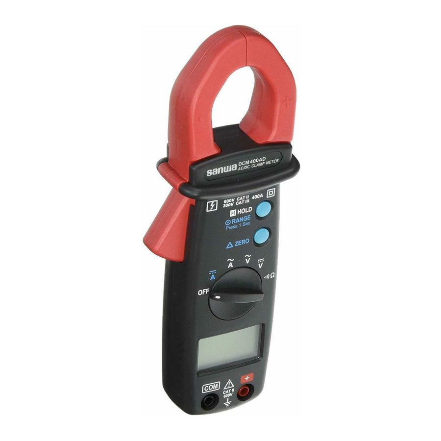
Instrument Familiarization

- Current Sensing Clamp
- Barrier
- Jaw-opening handle
- Main function selector
- LCD display
- COM input terminal
- Positive input terminal
- Data hold & Manual range button
- Zero button
- Battery lid
- Rear case
Symbol Definition

 | Low battery indication |  | Alternative source indication |
 | Auto range indication |  | Direct source indication |
 | Manual range indication |  | Resistance |
 | Hold Data indication |  | Polarity indication |
 | Continuity function indication |  | Analog bar graph indication |
 | Voltage measurement indication | ||
 | Current measurement indication | ||

Button Instruction
Zero Button
Press Zero button to enter the Zero mode, "![]() " annunciate turn on and Zero the display and the reading is stored as reference value for subsequent measurement.
" annunciate turn on and Zero the display and the reading is stored as reference value for subsequent measurement.
Press it again, the "![]() " annunciate blinking and memorized reference value will display.
" annunciate blinking and memorized reference value will display.
Press and hold down zero button for 2 second to exit the zero mode.
When the tester is under zero mode the auto range function will be disabled.
Data Hold & Manual Range Button
The user may hold the present reading and keep it on the display by pressing the "Hold" button.
When the hold data is no longer needed, one may release the data-hold operation by press "Hold" button again.
One may hold present reading by press the hold button instantaneously. One may also change the measuring scale range by press and hold the  RANGE button. When the decimal point changes, the user should release the button and scale range will stay at the setting range. If the user press and hold the button for more than 2 seconds, the tester will be in auto range mode again.
Disable Auto power off
Press and hold "ZERO" button and then the power on the meter.
Measuring Instruction
AC Current Measurement
Switch the main function selector to  range.
Open the clamp by pressing the jaw-opening handle and insert the cable to be measured into the jaw.
Close the clamp and get the reading from the LCD display.
Note:
Before this measurement, disconnect the test lead with the meter for safety. In some occasion that the reading is hard to read, push the HOLD button and read the result later.

DC Current Measurement
Switch the main function selector to  range.
Press ZERO button to enter the zero reading.
Before measuring current larger than 40A, adjust the scale to 400A range by press the range button and press ZERO button again.
Open the clamp by pressing the jaw-opening handle and insert the cable to be measured into the jaw.
Close the clamp and get the reading from the LCD display.
Note:
Before this measurement, disconnect the test lead with the meter for safety. In some occasion that the reading is hard to read, push the HOLD button and read the result later.

ACV Measurement

Maximum Input Voltage is 600V AC/DC. Do not attempt to take any voltage measurement that may exceed to avoid Electrical shock hazard and/or damage to this instrument.
Switch the main function selector to  range.
Connect red test lead to "+" terminal and black one to the " COM " terminal. Measure the voltage by touch the test lead tips to the test circuit where the value of voltage is needed.
Read the result from the LCD display.

DCV Measurement
Maximum Input Voltage is 600V AC/DC. Do not attempt to take any voltage measurement that may exceed to avoid Electrical shock hazard and/or damage to this instrument.
Switch the main function selector to  range.
Connect red test lead to "+" terminal and black one to the " COM " terminal. Measure the voltage by touch the test lead tips to the test circuit where the value of voltage is needed.
Read the result from the LCD display.

Resistance Measurement
Switch the main function to  range.
Connect red test lead to "+" terminal and black one to the " COM " terminal. Connect tip of the test leads to the points where the value of the resistance is needed.
Read the result from the LCD display.
Note:
When take resistance value from a circuit system, make sure the power is cut off and all capacitors need to be discharged.

Continuity Test
Switch the main function to  range.
Connect red test lead to "+" terminal and black one to the " COM " terminal. Connect tip of the test leads to the points where the conduction condition needed.
If the resistance is under 40Ω, the beeper will sound continuously.

Maintenance
- The following instructions are very important for safety. Read this manual thoroughly to ensure correct maintenance.
- Calibrate and inspect the meter at least once a year to ensure safety and maintain its accuracy.
- Maintenance and Inspection
- Appearance: Is the meter not damaged due to falling or other cause?
- Test leads:
- Are the core wires not exposed from the test leads?
- Is the plug when inserted to the input terminal not loose?
If any of the above problems exists, stop using the meter and request for repair.
- Inspection
Inspect the meter at least once a year. - Storage
- The panel and case are not resistant to volatile solvent and must not be cleaned with thinner or alcohol.
- The panel and case are not resistant to heat. Do not place the meter near heat-generating devices.
- Do not store the meter in a place where it may be subjected to vibration or where it may fall.
- Do not store the meter in places under direct sunlight, or hot, cold or humid places or places where condensation is anticipated.
- If the meter will not be used for a long time, remove the batteries.
- Battery when the meter is shipped:
A battery for monitoring has been installed prior to shipment from the factory. It may be discharged before the expiration of the described battery life.
*The battery for monitoring is a battery used to check the functions and performance of the product.
Battery Changing
To prevent electrical hazard or shock, turn off clamp meter and disconnect test leads before removing battery lid.
Never uses the meter before the battery lid is closed.

- When the battery voltage drop below proper operation range the
![]() will appear on the LCD display and the battery need to changed.
will appear on the LCD display and the battery need to changed. - Before changing the battery, switch the main dial to "OFF "and disconnect test leads. Open the battery lid by a screwdriver.
- Replace the old batteries with two LR03 or AAA size batteries.
 will appear on the LCD display and the battery need to changed.
SANWA ELECTRIC INSTRUMENT CO.,LTD.
Dempa Bldg, Sotokanda2-Chome Chiyoda-Ku, Tokyo, Japan


Documents / ResourcesDownload manual
Here you can download full pdf version of manual, it may contain additional safety instructions, warranty information, FCC rules, etc.
Advertisement


Need help?
Do you have a question about the DCM400AD and is the answer not in the manual?
Questions and answers