Table of Contents
Advertisement
Quick Links
Advertisement
Table of Contents

Related Manuals for Sanwa DCL1200R


Summary of Contents for Sanwa DCL1200R
- Page 1 DCL1200R DIGITAL CLAMP METER INSTRUCTION MANUAL...
-
Page 3: Table Of Contents
6-1 Maintenance and Inspection ………………………………017 6-2 Calibration and Inspection …………………………………017 6-3 Storage ………………………………………………………017 6-4 Battery Replacement ………………………………………017 【7】AFTER-SALE SERVICE 7-1 Warranty and Provision ……………………………………018 7-2 Repair ………………………………………………………019 7-3 SANWA web site ……………………………………………020 【8】SPECIFICATIONS 8-1 General Specifications ……………………………………021 8-2 Measuring Range and Accuracy …………………………022... -
Page 4: Explanation Of Warning Symbols
*Before use, read the following safety precautions. This instruction manual explains how to use your new digital clamp meter DCL1200R. Before use, please read this manual thoroughly to ensure correct and safe use. After reading it, keep it together with the product for reference to it when necessary. -
Page 5: Overload Protection
15. Never use the meter near equipment which generates strong electromagnetic waves or is charged. 16. Never use the meter if the meter or test leads are damaged or broken. 17. Never use the meter with the case or battery lid removed. 18. -
Page 6: Applications And Features 2-1 Applications
2-2 Features • Lighter than conventional clamp meters (30% reduction from Sanwa equivalent meters) for easy transportation. • TRUE RMS (AC coupling) • Large “HOLD” button to ensure holding of the indicated value. -
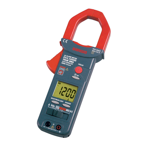
Page 7: Names And Functions Of Component Units 3-1 Names And Functions Of The Meter And Test Leads
[3] NAMES AND FUNCTIONS OF COMPONENT UNITS 3-1 Names and Functions of the Meter and Test Leads Test pin Finger guard Test probe (red) Test probe (black) Plug Clamp type current sensor A sensor to clamp a conductor to measure. (CT) (“Clamp sensor”) Accuracy guarantee range mark... - Page 8 When this button is pressed, the functions change as follows: V · Hz Position : DCV Position : 600 BACKLIGHT function : SELECT/ BACK LIGHT When the button is held pressured for 1 button second or longer, the backlight of the LCD will be turned on.
-
Page 9: Display
3-2 Display Numerical value indication. Unit of measurement. Lights during voltage measurement of low- input impedance by AUTO V· function. Negative sign of numerical data. Indication of AC measurement. Indication of DC measurement. Lights in the auto range mode. Lights in the data hold mode. Warning of low battery power: This mark will appear on the display when the built-in battery has been discharged and its voltage has dropped to... -
Page 10: Description Of Functions And Terms 4-1 Auto Power Off
[4] DESCRIPTION OF FUNCTIONS AND TERMS 4-1 Auto Power Off About 3 7 minutes after power on, the power will automatically be turned off and the display will become blank. However, if any of the following events occurs, the power will be turned off about 3 7 minutes after such event: a. -
Page 11: Crest Factor
4-3 Crest Factor The CR (crest factor) indicates the peak value of a signal by dividing it by its root-mean-square value. With most common waveforms such as sinusoidal wave and chopping wave, the crest factor is relatively low. With waveforms similar to low duty cycle pulse trains, the crest factor is high. - Page 12 [5] MEASURING PROCEDURE WARNING 1. Do not apply an input signal exceeding the maximum rated input of each function. 2. During measurement, do not change the function switch. 3. During measurement, do not hold a place beyond the barrier of the meter or the test pin side of the flange of the test leads.
-
Page 13: Ac Current (Aca) Measurement
5-2 AC Current (ACA) Measurement WARNING Remove the test leads from the measuring terminals to avoid electric shock. Function Maximum Rated Input Value Range AC 1200A 400.0A, 1200A measurement center SW position Accuracy guaranteed area Remarks: • This meter is of true RMS sensing (AC coupling). The accuracy guarantee range is as follows: Frequency range: 50/60 Hz Crest factor (CF) range: Full scale CF <... -
Page 14: Voltage (V) Measurement, Frequency (Hz) Measurement
5-3 Voltage (V) Measurement, Frequency (Hz) Measurement Function Maximum Rated Input Value Range ACV, DCV 600V 6.000V(6000mV), 60.00V, 600.0V Function Voltage range Sensitivity (Sinusoidal wave RMS) Frequency Measurement Range 6.000V Approx. 4V 10Hz 30kHz 60.00V Approx 30V 10Hz 1 kHz 600.0V Approx 60V 10Hz... - Page 15 5-4 Auto Resistance Voltage Determination (AUTO ·V) WARNING Because the initial input resistance is as low as 2.1 k , a very large amount of current will flow. Never use the meter for measuring circuits or devices having a small current capacity. For measurement of voltages that requires high input resistance, use the V function of V.Hz (input impedance 5 M ).
- Page 16 Remarks: • When there is no input, “AUTO” will be shown. When the RANGE button is pressed, the manual function will be set. • When there is no voltage input, a resistance value up to 6 M will be shown. When the RANGE button is pressed in this state, the manual range of the function will be set (“AUT”...
- Page 17 5-5 Resistance/Continuity Check (600 ), Diode Test ( Capacitance Measurement ( WARNING Never apply a voltage to the input terminals. 5-5-1 Resistance measurement / Continuity check (600 Function Maximum Rated Input Value Range Resistance measurement 600.0 Continuity check Remarks: • Buzzer response speed: <100 μs •...
- Page 18 Function Maximum Rated Input Value Range 100.0nF, 1000nF, 10.00μF, Capacitance( 2000μF 100.0μF, 2000μF Remarks: • 50.00 nF or below is out of the accuracy guarantee range. The accuracy drops to ±(12% rdg + 8 dgt) when the power supply voltage is in a range of 2.8 V and about 2.4 V (out of accuracy guarantee range) at which the battery low mark will light.
- Page 19 5-6 Voltage Detection ( Sensor Non-ground (hot) side Non-ground (hot) side Non-contact type Contact type SW position other than OFF. Remarks: • In any function switch position other than OFF, when the EF button is pressed, “E.F.” will be shown in the display and voltage detection can be started.
-
Page 20: Calibration And Inspection
If any of the above problems exists, stop using the meter and request for repair. 6-2 Calibration and Inspection For more information, please contact your dealer or Sanwa agent. 6-3 Storage CAUTION 1.The panel and case are not resistant to volatile solvent and must not be cleaned with thinner or alcohol. -
Page 21: After-Sale Service 7-1 Warranty And Provision
(1) year from the date of purchase. This warranty policy is valid within the country of purchase only, and applied only to the product purchased from Sanwa authorized agent or distributor. Sanwa reserves the right to inspect all warranty claims to determine the extent to which the warranty policy shall apply. -
Page 22: Repair
Please contact Sanwa authorized agent / distributor / service provider, listed in our website, in your country with above information. An instrument sent to Sanwa / agent / distributor without above information will be returned to the customer. Note :... -
Page 23: Sanwa Web Site
“Repair Product Enclosed” on the box surface. The cost of sending and returning the product shall be borne by the customer. 7-3 SANWA web site http://www.sanwa-meter.co.jp E-mail: exp_sales@sanwa-meter.co.jp — 20 —... -
Page 24: Specifications 8-1 General Specifications
[8] SPECIFICATIONS 8-1 General Specifications Operation method – method AC Sensing True RMS AC coupling 6000 counts Sampling rate 5 times/sec nominal Range selection Auto and Manual Over-range indication “OL” shown in numerical part. Polarity indication automatic selection “–” indicated only when negative input. Low battery indication “... -
Page 25: Measuring Range And Accuracy
8-2 Measuring Range and Accuracy Temperature: 23±5°C, humidity: 75% RH max., built-in battery voltage 2.4 V or above. rdg (reading): Read value, dgt (digit): Number of counts of last digit ACA (True RMS AC coupling) Range Accuracy 400.0A ±(1.7%rdg+5dgt) 1200A Remarks: •... - Page 26 ACV (True RMS AC coupling) Range Frequency range Accuracy Input Impedance 50Hz/60Hz ±(1.7%rdg+5dgt) 6.000V 50Hz 500Hz ±(2.2%rdg+5dgt) 50Hz/60Hz ±(1.7%rdg+5dgt) 60.00V Approx. 5M 50Hz 500Hz ±(2.2%rdg+5dgt) 50Hz/60Hz ±(2.2%rdg+5dgt) 600.0V 50Hz 500Hz ±(2.7%rdg+5dgt) Remarks: • Frequency range: 50Hz~500Hz • The accuracy guarantee range: In between 5 100% of measuring range •...
- Page 27 • The initial internal resistance is about 2.1k and at an input above 50V, the internal resistance increases rapidly. A guide for input voltages and internal resistance: 100V: 15k 300V: 100k 600V: 210k • Input is detected in the order of , DCV and ACV.
- Page 28 Voltage detection EF Remarks: • Frequency: 50Hz/60Hz • Detection sensor: ( ) mark part of clamp sensor (CT) • Voltage detection with test lead connected to + measuring terminal possible. • Input sensitivity : Approx. 20V or over — 25 —...
Need help?
Do you have a question about the DCL1200R and is the answer not in the manual?
Questions and answers