Table of Contents
Advertisement
Quick Links
[1] SAFETY PRECAUTIONS
*Before use, read the following safety precautions.
This instruction manual explains how to use
your digital leakage clamp meter DLC460F.
Before use, please read this manual thoroughly
to ensure correct and safe use. After reading it,
keep it together with the product for reference
to it when necessary.
Using the product in a manner not specified in
this manual may cause damage to the
protection function of the product.
The instructions given under the headings of
WARNING and
followed to prevent accidental burn and
electric shock.
1-1 Explanation of Warning Symbols
The meanings of the symbols used in this manual
and attached to the product are as follows:
DIGITAL LEAKAGE CLAMP METER
: Very important instructions for safe use.
The warning messages are intended to
prevent accidents to operating personnel
such as burn and electric shock.
The caution messages are intended to
prevent incorrect handling which may
INSTRUCTION MANUAL
damage the product.
: High voltage hazard
: Alternating current (AC)
: Direct current (DC)
: Resistance
: Backlight
SANWA ELECTRIC INSTRUMENT CO., LTD
: Double insulation or reinforced insulation
DempabBldg, 4-4 Sotokanda 2-Chome Chiyoda-ku, Tokyo, Japan
1-2 Warning Messages for Safe Use
01 1204 5001 6011
MEMO
The following instructions are intended to prevent
personal injury such as burn and electric shock.
Be sure to follow them when using the meter.
1. Never use the meter for the power lines
exceeding 600VAC to ground.
2. Voltages over 70VDC or 33Vrms AC (46.7V
peak) are hazardous to human body. Take
care so as not to touch them.
3. Never input signals exceeding the maximum
rated input value (see 1 3).
4. Never use the meter near equipment which
generates strong electromagnetic waves or is
charged.
5. Never use the meter if the meter or test leads
are damaged or broken.
6. Never use the meter with the case or battery
lid removed.
7. During measurement, keep your fingers
behind the finger guard of test leads and the
meter of the test leads.
8. To start measurement, do not change the
meter to another function or range nor replace
the plugs to other terminals.
9. During measurement, do not change function
switch of the meter nor replace the plugs to
other terminals.
10. Before starting measurement, make sure that
the function and range are properly set.
11. Never use the meter when it is wet or with wet
hands.
12. Be sure to use the specified type of test leads.
13. Never attempt repair or modification, except
for battery replacement.
14. Always conduct start up inspection and check
the meter at least once a year.
15. This meter is for indoor use only.
1-3 Overload Protection
The maximum rated input value and overload
protection have been established for the input
terminals of each function.
Input
Max. Rated
Function
Terminal
Input Value
DC/AC
DCV・ACV
600V
and
Do not input
voltage
ACmA
AC600 m A
CT
ACA
AC400 A
CAUTION must be
[2] APPLICATIONS AND FEATURES
2-1 Applications
This is a digital leakage clampmeter designed for
measurement in the ranges of CAT. III 600V. This
meter is useful for measuring leakage or load
current on power lines and equipment instrument.
2-2 Features
Safety design in compliance with the IEC61010 1.
Leakage current measurement Resolution 0.01mA
Low Pass Filter function
MAX MIN Hold Function
Backlight Function
: Ground
Data Hold, Auto Power Save Functions
Classification of overvoltage measurement
: Buzzer
Overvoltage measurement classification
(CAT. I): Line on the secondary side on the
inside of equipment via a transformer, etc. from
the receptacle.
Overvoltage measurement classification (CAT.
II): Line on the primary side of equipment with
power cord to be connected to the receptacle.
Overvoltage measurement classification
(CAT. III): Line from the primary side or branch
of equipment which directly takes in electricity
from a distribution board to the receptacle.
Overvoltage measurement classification
(CAT. IV): Line from the service conductor to
the distribution board.
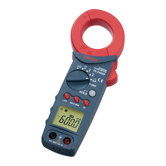
[3] NAMES OF COMPONENT UNITS
3-1 Main unit
Clamp Current
Transformer (CT)
Finger gurad
Trigger
Power and function
switch
Hold button
LPF button
MAX MIN button
Backlight button
Display
Input terminal ( )
Input terminal(+)
1
2
3-2 Display
Data Hold
LPF mode
Auto Power Save
mode
MAX MIN Hold
Max. Overload
DC
measurement
Protection
AC
measurement
Units
DC/AC
660 V
Minus polarity
Digit and
AC100 A
decimal point
AC450 A
Low battery indication
3-3 Test Lead
Removal test pins cover
Test probe(red)
Test pins
Finger guards
Plugs
Test probe(black)
In case of test pins cover attached: CAT.III 600V
In case of test pins cover removed: CAT.II 1000V
[4] DESCRIPTION OF FUNCTION
4-1 Power Switch and function switch
Turn this switch to turn on and off the power
and select a measuring function.
4-2 Date Hold function
When the HOLD button is pressed, the reading
indicated will be held with
on the display.
The indicated reading will not change if the
input signal is changed. When this button is
pressed again, the function will be disabled and
the meter will return to the measurement mode
without
on the display.
4-3 LPF function (mA/ACA)
When the LPF button is pressed,
turns
on the display. This function cuts current value
of high frequency. When this button is pressed
again, the function will be disabled and the
meter will return to the normal measurement
mode without
on the display.
Remarks:
Cut off frequency: 3 dB at 180 Hz
4-4 MAX/MIN function
When the MAX/MIN button is pressed, the
meter enter MAX/MIN mode, fix a measuring
range and turn
on. Press the button,
to read MAX, MIN, current reading sequence.
Press the button for 1 sec. or more to exit the
MAX/MIN mode.
3
Remarks:
5-2 Current Measurement (mA)
Function changes or functional operations will
cancel the function.
Remove the test leads from the measuring
4-5 BACKLIGHT function
terminals to avoid electric shock.
When the backlight button is pressed, the
backlight will be turned on. To disable the
function, the button is pressed again. The
Remarks:
backlight will be automatically turned off about
30 seconds after it was turned on.
Clamp the conductor (cable) to measure at the
center of the trans core (CT).
4-6 AUTO POWER SAVE function
To measure zero phase current, clamp only
The meter will go to AUTO POWER SAVE
earth wire or all of wires like 2 core or 3 core
function to save battery life about 30 minutes
wire together.
after last function switch or button operation. To
The meter may malfunction in places where a
wake up the meter, press any button. To disable
strong magnetic field is present.
the function, press any button.
Do not apply voltage and current at the same
Remarks:
time.
Even in the AUTO POWER SAVE mode, the
tiny power is still consumed. When the meter is
not going to be used for an extended period of
time, be sure to turn off the power switch.
Load current
To disable the function, turn the function switch
clamp one wire
to position other than OFF while holding the
HOLD button.
on the display is turned off
when Auto Power Save function is disabled.
4-7 Low Battery indication
When the built in batteries have been
discharged and the voltage has dropped to
below about 2.2V,
appears in the display.
When the mark flickers or lights, replace both
two batteries with new ones.
[5] MEASURING PROCEDURE
Zero-phase current
clamp all of wires
1. Do not apply an input signal exceeding the
maximum rated input of each function.
2. During measurement, do not change the
function switch.
3. During measurement, keep your finger behind
finger guard of the test lead and the meter.
4. When measurement has been finished, remove
the test leads and CT from the object measured
and turn the function switch to OFF position.
5-1 Start-up Inspection
Always conduct the start up inspection to ensure
safety.
1. Be sure that when the meter is turned on, the
low battery indication
is not flickering or lit.
If it is flickering or lit, replace the battery with a
Zero-phase current
new ones.
clamp earth wire
2. Do not use the meter if the meter or test lead is
damaged or broken.
3. Make sure the test leads are not cut.
4. Make sure the meter and your hand are not
wet.
4
ACmA current measurement
ACmA current measurement
ACmA current measurement
5
Advertisement
Table of Contents

Subscribe to Our Youtube Channel
Related Manuals for Sanwa DLC460F


Summary of Contents for Sanwa DLC460F
- Page 1 Remove the test leads from the measuring This instruction manual explains how to use mode MAX MIN Hold 4-5 BACKLIGHT function terminals to avoid electric shock. your digital leakage clamp meter DLC460F. Input Max. Rated Max. Overload Function When the backlight button is pressed, the...
- Page 2 Buzzer sounds : Less than 30 ohms center of the trans core (CT). To avoid electric shock, do not remove the battery instrument sent to Sanwa / agent / distributor Power supply: LR03 x 2 pcs. Open voltage’ approx. 0.9V...
Need help?
Do you have a question about the DLC460F and is the answer not in the manual?
Questions and answers