Table of Contents
Advertisement
Advertisement
Table of Contents

Related Manuals for Sanwa DCL1000


Summary of Contents for Sanwa DCL1000
- Page 1 DCL1000 DIGITAL CLAMP METER INSTRUCTION MANUAL...
- Page 3 6-1 Maintenance and Inspection ⋯⋯⋯⋯⋯⋯⋯⋯⋯⋯⋯⋯013 6-2 Calibration and Inspection ⋯⋯⋯⋯⋯⋯⋯⋯⋯⋯⋯⋯⋯013 6-3 Storage ⋯⋯⋯⋯⋯⋯⋯⋯⋯⋯⋯⋯⋯⋯⋯⋯⋯⋯⋯⋯⋯013 6-4 Battery Replacement ⋯⋯⋯⋯⋯⋯⋯⋯⋯⋯⋯⋯⋯⋯⋯013 【7】AFTER-SALE SERVICE 7-1 Warranty and Provision ⋯⋯⋯⋯⋯⋯⋯⋯⋯⋯⋯⋯⋯⋯014 7-2 Repair ⋯⋯⋯⋯⋯⋯⋯⋯⋯⋯⋯⋯⋯⋯⋯⋯⋯⋯⋯⋯⋯015 7-3 SANWA web site ⋯⋯⋯⋯⋯⋯⋯⋯⋯⋯⋯⋯⋯⋯⋯⋯⋯016 【8】SPECIFICATIONS 8-1 General Specifications ⋯⋯⋯⋯⋯⋯⋯⋯⋯⋯⋯⋯⋯⋯017 8-2 Measuring Range and Accuracy ⋯⋯⋯⋯⋯⋯⋯⋯⋯⋯018...
-
Page 4: Safety Precautions
*Before use, read the following safety precautions. This instruction manual explains how to use your new digital clamp meter DCL1000. Before use, please read this manual thoroughly to ensure correct and safe use. After reading it, keep it together with the product for reference to it when necessary. - Page 5 5. Never use the meter near equipment which generates strong electromagnetic waves or is charged. 6. Never use the meter if the meter or test leads are damaged or broken. 7. Never use the meter with the case or battery lid removed. 8.
-
Page 6: Applications And Features
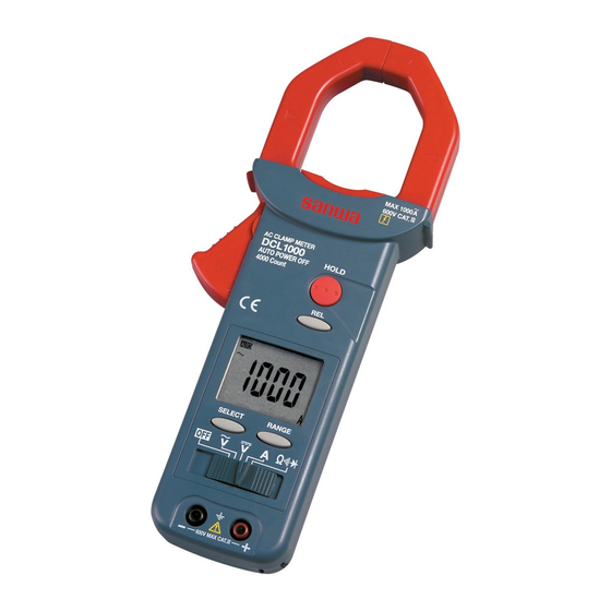
2-2 Features ・Lighter than conventional clamp meters (30% reduction from Sanwa equivalent meters) for easy transportation. ・Large “ ” button to ensure holding of the indicated value. ・Safety design in compliance with the IEC. - Page 7 [3] NAMES AND FUNCTIONS OF COMPONENT UNITS 3-1 Names and Functions of the Meter and Test Leads Testpin Finger guard Test probe (red) Test probe (black) Plug A sensor to clamp a conductor to Clamp type current sensor (CT) measure. (“Clamp sensor”) Accuracy guarantee range mark A range to clamp a conductor to measure which is guaranteed for accuracy.
-
Page 8: Power Switch
When the button is pressed, button the functions change as follows: Position: → → → Power switch & Slide this switch to turn on and off the function switch power and to select a function. --- measuring terminal Insert the black test lead. + measuring terminal Insert the red test lead. - Page 9 3-2 Display Numerical value indication. Negative sign of numerical data. Indication of AC measurement. Indication of DC measurement. Lights in the auto range mode. Not used. Lights when the diode test function is used. Lights when the continuity check function is used. Lights in the data hold mode.
-
Page 10: Measuring Procedure
[4] DESCRIPTION OF FUNCTIONS AND TERMS 4-1 Auto Power Off If no switch or button is operated for about 30 minutes after power on, the power will automatically be turned off and the display will become blank. To reset the meter, press any button or remove the test leads or the clamp sensor (CT) from an object to measure and set the function switch to OFF. - Page 11 5-1 Start-up Inspection CAUTION 1. Be sure that when the power switch is turned on, the battery low warning mark ( ) is not flickering or lit. If it is flickering or lit, replace the battery with a new one. (See 6-4.) 2.
- Page 12 5-2 Current (ACA) Measurement WARNING Remove the test leads from the measuring terminals to avoid electric shock. Function Max rated input value Range AC 1000A 400.0A, 1000A ACA measurement Center SW position Accuracy guaranteed area Remarks: • This meter is of average value response. Frequency range: 50/60 Hz (Sinusoidal wave AC) •...
- Page 13 5-3 Voltage (V) measurement Function Max rated input value Range DC 600V 400.0mV, 4.000V, 40.00V, 400.0V, 600V AC 600V 400.0mV, 4.000V, 40.00V, 400.0V, 600V ACV measurement DCV measurement SW position SW position Remarks: • Average value response and the frequency range is 50/60 Hz. •...
- Page 14 5-4 Resistance, Continuity Buzzer and Diode ( WARNING Never apply a voltage to the input terminals. 5-4-1 Resistance ( ) measurement Function Max rated input value Range 400.0Ω, 4.000kΩ, 40.00kΩ, 40.00MΩ 400.0kΩ,4.000MΩ, 40.00MΩ Open circuit voltage: Approx. 0.4 VDC 5-4-2 Continuity check ( Measuring range: 0 400.0 Ω...
- Page 15 5-4-1 Resistance 5-4-2 measurement Continuity check Resistor 5-4-3 Diode test SW position Good:Forward Good:OL shown Bad : Other voltage drop indication shown Bad : 0.000V shown forward diase reverse diase Each time the SELECT button is pressed, the functions change as indicated by in the figure.
-
Page 16: Maintenance
If any of the above problems exists, stop using the meter and request for repair. 6-2 Calibration and Inspection For more information, please contact your dealer or Sanwa agent. 6-3 Storage CAUTION 1. The panel and case are not resistant to volatile solvent and must not be cleaned with thinner or alcohol. -
Page 17: After Sales Service
(1) year from the date of purchase. This warranty policy is valid within the country of purchase only, and applied only to the product purchased from Sanwa authorized agent or distributor. Sanwa reserves the right to inspect all warranty claims to determine the extent to which the warranty policy shall apply. - Page 18 7. Where you purchased the product Please contact Sanwa authorized agent / distributor / service provider, listed in our website, in your country with above information. An instrument sent to Sanwa / agent / distributor without above information will be returned to the customer. Note:...
- Page 19 “Repair Product Enclosed” on the box surface. The cost of sending and returning the product shall be borne by the customer. 7-3 SANWA web site http://www.sanwa-meter.co.jp E-mail: exp_sales@sanwa-meter.co.jp — 16 —...
-
Page 20: Specifications
Max. 42 mm clamp size Dimensions 238(L) X 95(W) X 45(H) mm Weight Approx. 290g (battery included) Auto power off About 30 min. after power on. Accessories Battery (built-in), test leads (TL-23), carrying case (C-DCL1000), instruction manual — 17 —... -
Page 21: Measuring Range And Accuracy
8-2 Measuring Range and Accuracy Temperature: 23±5˚C, humidity: 75% RH max., built-in battery voltage 2.4 V or above. rdg (reading): Read value, dgt (digit): Number of counts of last digit Range Accurac Remarks ・ This meter is of average value response. 400.0A ±(1.7%rdg+5dgt)... - Page 22 Range Frequency range Accuracy Input Impedance Remarks 400.0mV ±(4.2%rdg+5dgt) 50Hz∼500Hz ±(2.2%rdg+5dgt) 50Hz/60Hz 4.000V The AC ±(2.7%rdg+5dgt) 60Hz∼500Hz ±(2.2%rdg+5dgt) 400.0mV range 50Hz/60Hz Approx. 10MΩ 40.00V ±(2.7%rdg+5dgt) is set with the 60Hz∼500Hz ±(2.2%rdg+5dgt) RANGE button. 50Hz/60Hz 400.0V ±(2.7%rdg+5dgt) 60Hz∼500Hz 600V ±(3.2%rdg+5dgt) 50Hz∼500Hz It may malfunction when measuring voltage/current in the inverter circuit.
- Page 23 本社 = 東京都千代田区外神田2−4−4・ ・ 電波ビル 郵便番号 = 101-0021・ ・ 電話 = 東京 (03) 3253−4871㈹ 大阪営業所 = 大阪市浪速区恵美須西2−7−2 郵便番号 = 556-0003・ ・ 電話 = 大阪 (06) 6631−7361㈹ SANWA ELECTRIC INSTRUMENT CO.,LTD. Dempa Bldg., 4-4 Sotokanda2-Chome Chiyoda-Ku,Tokyo,Japan ① 2006.04 狠...
Need help?
Do you have a question about the DCL1000 and is the answer not in the manual?
Questions and answers