Table of Contents
Advertisement
Quick Links
Advertisement
Table of Contents

Related Manuals for Sanwa MT-5


Summary of Contents for Sanwa MT-5
- Page 2 If the receiver or a servo sinks in the water, immediately collect it and dry the interior. When the interior is dry, please submit it to the Sanwa Service for inspection even if it performs normally.
- Page 3 Caution Handling Transmitter Warning Careful When Driving When operating an RC car, please make sure to follow Please do not hit, drop or cause strong shocks. In addition, if you touch the transmitter, receiver, servo, the following notes and avoid giving trouble to others. FET speed controller, etc.
- Page 4 ● MT-5 do not have automatic power off system. The transmitter would not be turned off until switching off. Please make sure to switch off the transmitter when finishing to use the transmitter.
- Page 5 INDEX ■Structure and the Standard of the Set ・ ・ ・ ・ ・ ・ ・ ・ ・ ・ ・ ・ ・ ・ ・ ・ ・ ・ ・ ・ ・ ・ ・ ・ ・ ・ ・ ・ ・ ・ ・ ・ ・ ・ ・ ・ ●Structure of the set (5) ●Set specification (5) ■Before Using ・...
- Page 6 Structure and the Standard of the Set STRUCTURE OF THE SET MT-5 RX-493i PC (Primary Component) <A> Transmitter MT-5(TX-491) <B> Receiver RX-493i <C> Servo <D> Accesories Strap Hook x1 Trigger Angle Spacer x2 Brake Trigger +1/+2 x each 1 Grip Pad S size x1...
- Page 7 Before Using ADJUSTING THE STEERING AND THROTTLE TENSION MT-5 can adjust the tension of the steering/throttle trigger to match operation of the steering/throttle to the user’s preference. Adujsting the Steering Tension By inserting a hex wrench driver (1.5mm) to the place where the arrow is pointing at in the illustration on the right and turning, you can adjust the tension of the steering spring.
- Page 8 Before Using ADJUSTING THE FULL ADJUSTABLE TRIGGER Adjusting the trigger position Loosen the fixing screws of the trigger on the back of the transmitter. Then, adjust the adjusting screw of the trigger position on the back of the transmitter to set the trigger at the position of your preference.
- Page 9 ABOUT MICRO SD CARD ● MT-5 is compatible to Micro SD Cards. By using a Micro SD Card, it is possible to save model data and telemetry data. Also, it is possible to do firmware update using a Micro SD Card when a firmware update of MT-5 is released.
- Page 10 Throttle neutral position or operation quantities might be different each transmitter. Please adjust each transmitter setting to fit chassis linkage. When setting SSL compatible devices by MT-5 CODE AUX function, please connect SSL compatible device to SSL port. MUST set fail-safe setting on each transmitter.
- Page 11 • For R/C System parts such as the transmitter, receiver, servos, ESC (FET Speed Controller) and transmitter battery, use genuine SANWA products. *When combining products other than genuine SANWA products, modifying, adjusting or exchanging parts is done at a place other than SANWA, we do not take any responsibility.
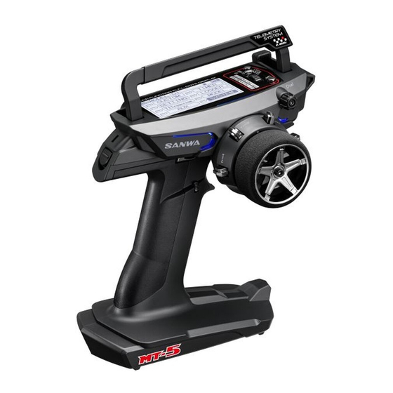
- Page 12 Names of each part of transmitter Carrying Handle (Movable) Display Panel *LED will be on when Telemetry is ON and Receiver Battery is OFF. LED will be flashing while Telemetry alarm is active. Select Button Multi-Selector Back Button Function LED Trim 1 Trim 2 Steering Wheel...
- Page 13 Power Switch Trigger Position Adjusting Screw When using the Strap Hook Internal Antenna Strap Hook Micro SD cover Remove the screw, attach the hook & tighten the screw *Make sure that the hook is facing the right direction Grip (Normal/Small) Throttle Trigger Connector Cover...
- Page 14 Indicator Function (RX-DATA) ● MT-5 can check signal receiving conditions to use with RX-493i. The conditions can be used for devices glitch and checking receiver place on the car. There are 2 different types of data for checking signal condition.
- Page 15 Batteries are placed improperly. recharged batteries. Reinstall the batteries as the polarity is indicated. Power is cut off Bad connection of connectors. Bring to Sanwa Service occasionally. Replace with new batteries or Insufficient length Batteries are consumed. recharged batteries. If the problem cannot be solved, please contact Sanwa Service Alarm will not stop.
- Page 16 Troubleshooting Guide on Page 64. If you require further help that cannot be solved using The Troubleshooting Guide, or if you have technical questions, please contact SANWA service center in your region. For a complete list of distributors in your rgion, please visit www.sanwa-denshi.com/rc/distributors.html.
- Page 17 Before Using ADJUSTING THE STEERING AND THROTTLE TENSION MT-5 can adjust the tension of the steering/throttle trigger to match operation of the steering/throttle to the user’s preference. Adujsting the Steering Tension By inserting a hex wrench driver (1.5mm) to the place where the arrow is pointing at in the illustration on the right and turning, you can adjust the tension of the steering spring.
- Page 18 Before Using ADJUSTING THE FULL ADJUSTABLE TRIGGER Adjusting the trigger position Loosen the fixing screws of the trigger on the back of the transmitter. Then, adjust the adjusting screw of the trigger position on the back of the transmitter to set the trigger at the position of your preference.
- Page 19 ABOUT MICRO SD CARD ● MT-5 is compatible to Micro SD Cards. By using a Micro SD Card, it is possible to save model data and telemetry data. Also, it is possible to do firmware update using a Micro SD Card when a firmware update of MT-5 is released.
- Page 20 Throttle neutral position or operation quantities might be different each transmitter. Please adjust each transmitter setting to fit chassis linkage. When setting SSL compatible devices by MT-5 CODE AUX function, please connect SSL compatible device to SSL port. MUST set fail-safe setting on each transmitter.
- Page 21 • For R/C System parts such as the transmitter, receiver, servos, ESC (FET Speed Controller) and transmitter battery, use genuine SANWA products. *When combining products other than genuine SANWA products, modifying, adjusting or exchanging parts is done at a place other than SANWA, we do not take any responsibility.
- Page 22 Names of each part of transmitter Carrying Handle (Movable) Display Panel *LED will be on when Telemetry is ON and Receiver Battery is OFF. LED will be flashing while Telemetry alarm is active. Select Button Multi-Selector Back Button Function LED Trim 1 Trim 2 Steering Wheel...
- Page 23 Power Switch Trigger Position Adjusting Screw When using the Strap Hook Internal Antenna Strap Hook Micro SD cover Remove the screw, attach the hook & tighten the screw *Make sure that the hook is facing the right direction Grip (Normal/Small) Throttle Trigger Connector Cover...
- Page 24 ABOUT POWER ON ALARM ● MT-5 displays “No Operation” with a warning alarm after 10 minutes of no steering wheel, throttle trigger and switches. Alarm is turned off, if the steering wheel, throttle trigger or a switch is operated. In case you do not use them, turn the power switch off.
- Page 25 ABOUT DISPLAY PANEL ● Each feature of MT-5 allows you to directly select a feature with the Multi-Selector. ● You can set up each channel feature separately. ● As you turn the power switch on, the top screen launches after the boost screen is displayed(when the boot setting is on).
- Page 26 How to Use Each Feature ABOUT THE MENU STRUCTURE ● The user can set up features and do model memory call easily by using each key. ● The Menu consists of Setting, AUX, CUSTOM, MODEL, TELEMETRY, TH-FUNCTION, TIMER and SYSTEM, and related features are included in each menu. CUSTOM SETTING TH‑FUNCTION...
- Page 27 ABOUT SHORT CUT MENU ● MT-5 has a feature of Short Cut Menu that is launched as the user performs key operation when operating the power switch. When you turn the power switch on with holding on the Back Button, it becomes the Direct Model Select.
- Page 28 How to Use Each Feature ABOUT SHORT CUT MENU QUICK SETUP WIZARD ● Quick Setup 1) Turn the power switch on while doing Enter operation. Power Switch ON Push ⇒ Holding Holding 2 ) Quick Setup screen is displayed. As you do Enter operation, Quick Setup Wizard is launched.
- Page 29 BACK Initialization (Model Initialization) screen.Do initialization following the message. 6 ) When initializing (Initializing Model) is completed, the screen changes to RF Mode Selection Screen. MT-5 is only compatible FH5 RF mode. ○Default: FH5 ・ Compatible Receivers: FH5 RX-491,RX-492,RX-493,RX-493i ENTER...
- Page 30 How to Use Each Feature DUAL RATE [ D/R ] SETTING ● You can adjust rudder angle when operating the steering wheel and throttle trigger to their peak. To correspond to the RC car or road condition, adjust the rudder angle as you operate. *You can adjust steering for both right and left at the same time and throttle separately for high and brake sides.
- Page 31 SPEED SETTING ● Features to control the speed of the servos used for steering and throttle. By setting, the RC car is not affected even when doing a sudden operation. On the steering side, smooth corner work becomes possible and on the throttle side, stable rising from a corner by throttle work with saved power. *When setting AUX TYPE to [CODE5/CODE10], adjusting the speed feature of the AUX channel does not affect the performance.
- Page 32 How to Use Each Feature CURVE SETTING ● Function of making operation volume of servo variable with respect to the operation of the steering wheel, throttle trigger, AUX. It responds quickly when the set value is on plus (+) side whereas it responds mildly when the set value is on minus (-) side.
- Page 33 [ TH ] THROTTLE EXPONENTIAL ● You can change the throttle feature from Mild to Linear and to Quick. In general, when operating on a slippery road or if you find over powering, change the setting to the minus side and when operating on a high-grip road or if you find lack of power in the power unit, change to the plus side.
- Page 34 How to Use Each Feature CURVE SETTING [ ST ] STEERING ADJUSTABLE RATE CONTROL ● You can change the steering feature from Mild to Linear and to Quick. In general, if you find your RC car oversteering, change the setting to the minus side and if you find understeering, change to the plus side.
- Page 35 [ AUX1 ] AUX1 ・ ADJUSTABLE RATE CONTROL ● You can change the AUX1 performance feature from Mild to Linear and to Quick. You can set the High side and the Low side separately. *When setting AUX1 to [CODE5/CODE10] in AUX TYPE, changing the setting does not affect the performance.
- Page 36 How to Use Each Feature FAIL SAFE [ F/S ] SETTING ● Fail Safe Operation is a feature to keep the servos in a predetermined position for each channel in the event that the receiver cannot receive a signal from the transmitter. A feature to keep the servos in a predetermined position for the servo of the throttle channel (2ch) in the event that the battery voltage on the receiver side of an engine RC car goes below the set voltage is Battery Fail Safe Operation.
- Page 37 Neutral position adjustment is necessary not only after installing the servo but for changes that happen during running such as tire wears and chassis twist. MT-5 Trim features two types of Trim including Center Trim that adjusts only the neutral position without changing the end of the operating angle and Parallel Trim that moves the end of the operating angle and the neutral position simultaneously.
- Page 38 How to Use Each Feature BASE SETTING ● Base [BASE] is a feature to integrate features of Sub Trim that adjusts the direction of the servo of each channel and the speed controller according to a specific RC car and the End Point Adjustment [EPA] that sets the operating quantity into one feature (Base) to allow you to make a setting all at once.
- Page 39 AUX1 ・ END POINT ADJUSTMENT AUX1-EPA ● You can use AUX1 for functions of accessories and adjust the maximum steering angle (operating quantity) with EPA. Since you can set H/L separately, precise adjustment is possible. *When setting AUX1 to [CODE5/CODE10] in AUX TYPE, the operation will not be refected even by adjusting EPA.
- Page 40 How to Use Each Feature TRIM SETTING ● For Trim, you can adjust Trim for each channel and set the Trim action (center/parallel). TRIM ● Correct neutral (center) of each channel (ST/TH/AUX1/AUX2) with Trim. ● As default, steering is set for Trim 1 (TRM1), and throttle for Trim 2 (TRM2). 1) Select a channel (ST/TH/AUX1/AUX2) for adjusting Trim with the Select button.
- Page 41 CONVERT ● A feature to convert Trim that has been adjusted in each channel to Sub Trim and EPA and to correct Trim to center. Depending on a setting, there is a case you cannot convert. 1) Select a channel (ST/TH/AUX1/AUX2) to convert with the Select button.
- Page 42 How to Use Each Feature THROTTLE FUNCTION ● The throttle function allows you to adjust the setting values of ALB (Anti-Lock Brake), OFFSET and TH TYPE (throttle type) of the throttle channel. ANTI-LOCK BRAKE [ ALB ] THROTTLE FUNCTION ● Anti-Lock Brake enables stable braking on a low grip road. ●...
- Page 43 OFFSET THROTTLE FUNCTION ● By moving the position of the throttle neutral at the time of starting a nitro RC car engine, it improves the start-up performance of the engine. ● You can fix at a position where idling speed is increased so that the engine will not stop during refueling your nitro RC car.
- Page 44 How to Use Each Feature ● AUX is a feature to set the performance of AUX1 and AUX2 (3ch, 4ch). You can choose from STEP AUX (STEP), POINT AUX (POINT), 4WS (4-Wheel Steering: Coordinate Phase, Opposite Phase). MOA (Motor On Axle), AUX-MIX (AUX Mixing: ST → AUX/TH-AUX) and CODE5/CODE10 (Code Communication). *Setting of AUX TYPE is done in the System Menu.
- Page 45 4-WHEEL STEERING ● With the operation of assigned Trim or Switch, control the motion of the 4 Wheel Steering. 1) Select [AUX] with the multi-selector and define with the Enter operation. 2) Setting Operating Mode Set the Operating Mode of 4WS with the multi-selector. Set the Operating Mode according to the usage.
- Page 46 How to Use Each Feature ● AUX is a feature to set the performance of AUX1 and AUX2 (3ch, 4ch). You can choose from STEP AUX (STEP), POINT AUX (POINT), 4WS (4-Wheel Steering: Coordinate Phase, Opposite Phase). MOA (Motor On Axle), AUX-MIX (AUX Mixing: ST → AUX/TH-AUX) and CODE5/CODE10 (Code Communication). *Setting of AUX TYPE is done in the System Menu.
- Page 47 *In case of setting CODE5/CODE10 on AUX TYPE, CODE AUX setting condition will display on top screen as below pictures. *Please check CODE5/CODE10 compatible devices on SANWA HP. Please check each compatible device user manual about detail setting for the each device.
- Page 48 How to Use Each Feature TIMER ● It has three timer features including Lap Timer, Interval Timer and Down Timer. ● When selecting a timer and operate the Select button, you can toggle between the timer screen and the setting screen. *When a timer is activated, X Illumination and Function LED flash.
- Page 49 5) Setting START Set the Timer Start from the Trigger Interlock/Switch/Random. ○ Setting Range: TRIGGER/KEY/STARTER ○ Default: TRIGGER Function LED 6) Setting DATA-LOG X Illumination It sets Telemetry Data Log (record) along with the timer. ○ Setting Range: ON/OFF ○ Default: ON *Log starts along with the timer feature.
- Page 50 How to Use Each Feature INTERVAL TIMER TIMER ● It activates the alarm at the time set at the beginning of running and uses it as the guideline for the goal time. 1) Select [TIMER] with the multi-selector and determine with the Enter operation.
- Page 51 ● To use the Telemetry feature, you can make it compatible by using a compatible receivers, SUPER VORTEX series / Gen2 / PRO / SV-D2. * Telemetry data is only capable with SANWA compatible devices. Telemetry data cannot be displayed in case of using other manufacture products.
- Page 52 How to Use Each Feature VIEW DATA TELEMETRY ● A menu to read the recorded log data and creates a graph. 1) Select [LOG DATA] with the multi-selector and determine with the Enter operation. 2) Select LOG DATA to create a graph and determine with the Enter operation.
- Page 53 EXPORT [ .CSV ] TELEMETRY ● A feature to convert the selected log data to a graph with PC (Personal Computer) software such as a spreadsheet software. ● Please note that data converted by the Export feature cannot be converted to a graph with the transmitter. ●...
- Page 54 How to Use Each Feature TELEMETRY TELEMETRY SETTING TELEMETRY ● Set each feature of Telemetry. Select the feature to set with the select button. • TLM1/TLM2: Received conidition, temprature, telemetry data setting. In case of selecting TL-DATA [NAME]: Up to 3 characters of data names of TLM1/TLM2 are changeable.
- Page 55 GRAPH SETTING TELEMETRY ● A feature to select 3 items to be displayed in a graph when displaying Telemetry data as a graph. 1) Select [TELEMETRY] with the multi-selector and determine with the Enter operation. 2) Setting GRAPH SETTING Select [GRAPH SETTING] with the multi-selector and determine with the Enter operation.
- Page 56 <1>To the Model Screen SUPPLEMENT MT-5 has a feature of Direct Model Select. When turning the power switch of the transmitter on while pressing the Back button, it starts from the MODEL SELECT screen so that you can easily call a...
- Page 57 MODEL NAME ● You can register a model name with up to 12 characters of alphabets, numbers, EU Font and symbols for each model. 1) Select [MODEL] with the multi-selector and determine with the Enter operation. 2) Setting Model Name [MODEL NAME] Select [MODEL NAME] with the multi-selector and ENTER BACK...
- Page 58 How to Use Each Feature MODEL MENU MODEL ● You can set the features about Model Select, Model Name, Model Copy and Model Clear. ● Installed with high capacity EEPROM and it can memorize data for 20 models of M01 ~ M20. MODEL COPY ●...
- Page 59 ● About copying from a micro SD card When performing Model Copy, the main body memory and a micro SD card can select designation of the copy source and the copy destination. When selecting a Model on the copy destination selection screen, you can select with the Select button operation.
- Page 60 BACK 3) Setting RF MODE (Signal output system) ○ Output System ・ FH5 RX-491,RX-492, RX-493, RX-493i *FH4, FH3, FH2, FH-E, DS mode receivers are not compatible with MT-5. ENTER BACK Confirmation Screen 4) Setting TELEMETRY Set TELEMETRY with the multi-selector.
- Page 61 BL-SIGMA, SV-08, HV-10, HV-12 and F2500 work in NOR/SHR mode. 7) Setting BIND ● What is BIND: Each of MT-5 transmitters has its own unique ID (solid identification) number. BIND is to let the receiver memorize the ID number. Operation will be possible only between the transmitter and the receiver that completed Binding.
- Page 62 How to Use Each Feature SYSTEM MENU SYSTEM Positions of the Switch and Trim TRIM1 TRIM2 TRIM4 Features assgined to the Switch and Trim at the factory TR1:Steering Trim(TRM-ST) TR2:Throttle Trim(TRM-TH) TR3:Dual Rate ST(D/R-ST) DIAL TR4:Dual Rate BR(D/R-BR) TRIM3 SW1:Timer (TIMER) SW2:CUSTOM SWITCH2 PUSH SWITCH1...
- Page 63 KEY ASSIGN TRIM ● You can change the setting value of each feature with Trim1 - Trim4. ● You can also change the setting of the variation change in one time of Trim operation with the STEP setting and the direction of the action with the REV setting. 1) Select [SYSTEM] with the multi-selector and determine with the Enter operation.
- Page 64 How to Use Each Feature SYSTEM MENU SYSTEM CUSTOM-LIST ● By setting an often-used menu onto the custom list, you can build your favorite menu. You can create a custom list for each model memory and you can create a 4-page list. ●...
- Page 65 AUX TYPE ● A feature to set the performance of AUX1 and AUX2 (3ch and 4ch). 1) Select [SYSTEM] with the multi-selector and determine with the Enter operation. 2) Select [AUX TYPE] with the multi-selector and determine with the Enter operation. 3) Set AUX TYPE with the multi-selector.
- Page 66 How to Use Each Feature SYSTEM MENU SYSTEM RACING MODE ● A feature to adjust the running characteristics of your RC car by switching the Racing Mode so that the features compatible to the Racing Mode can respond to your RC car and road conditions. ●...
- Page 67 LIMIT VOLT:2.7 ~ 5.0v ○ Default: DRYx3 (AAA x3) *MT-5 do not have automatic power off system. Please make sure turning off when finishing to use the transmitter. BUZZER ● You can set operating sounds of key operation, Trim and Switch and the buzzer scales.
- Page 68 How to Use Each Feature SYSTEM MENU SYSTEM ● You can set LCD (Liquid Crystal) contrast (intensity), brightness and lighting mode (lighting time) of Back Light. 1) Select [SYSTEM] with the multi-selector and determine with the Enter operation. 2) Select [LCD] with the multi-selector and determine with the Enter operation.
- Page 69 CLOCK ● A menu to control the calendar and the clock display on the top screen and the time used. ● There are resettable [ON TIME1] that is a guideline for replacing and recharging the batteries and [ON TIME2] that is a guideline for overhaul of the main body unit.
- Page 70 ● About Steering wheel angle adjustment ENTER MT-5 can adjust steering wheel angle. Please take off wide steering pad and put hex screws in accesory box on holes of steerig wheel (there are 2 holes at steering wheel). Please adjust steering angle by the hex screws.
- Page 71 *Compatible Micro SD card capacity is maximum 32GB. Other manufacture Micro SD card might not be able to use. Please use Micro SD card by SANWA. Unless you insert a micro SD card, it will not be displayed.
- Page 72 Assign Function List Screen Display Name of the Features TRIM/Dial ---(No assigned feature) - ○ ○ ASSIST-ST Steering Drive Assistance TRIM-ST Steering Trim ○ - - TRIM-TH Throttle Trim ○ - - TRIM-A1 AUX1 Trim ○ - - ○ - -...
- Page 73 Indicator Function (RX-DATA) ● MT-5 can check signal receiving conditions to use with RX-493i. The conditions can be used for devices glitch and checking receiver place on the car. There are 2 different types of data for checking signal condition.
- Page 74 INDEX Anti-Lock Brake [ALB] ・ ・ ・ ・ ・ ・ ・ ・ ・ ・ ・ ・ ・ ・ ・ ・ ・ ・ ・ ・ ・ ・ ・ ・ ・ ・ ・ ・ ・ ・ ・ ・ ・ ・ ・ ・ ・ ・ ・ ・ ・ ・ ・ ・ ・ ・ ・ ・ P.31 AUX ・...
- Page 75 Batteries are placed improperly. recharged batteries. Reinstall the batteries as the polarity is indicated. Power is cut off Bad connection of connectors. Bring to Sanwa Service occasionally. Replace with new batteries or Insufficient length Batteries are consumed. recharged batteries. If the problem cannot be solved, please contact Sanwa Service Alarm will not stop.
- Page 76 Troubleshooting Guide on Page 64. If you require further help that cannot be solved using The Troubleshooting Guide, or if you have technical questions, please contact SANWA service center in your region. For a complete list of distributors in your rgion, please visit www.sanwa-denshi.com/rc/distributors.html.
- Page 77 FCC COMPLIANCE STATEMENT This equipment has been tested and found to comply with the limits for a Class B digital device, pursuant to Part 15 of the FCC Rules. These limits are designed to provide reasonable protection against harmful interference in a residential installation. This equipment generates, uses, and can radiate radio frequency energy and, if not installed and used in accordance with the operating instructions, may cause harmful interference to radio communications. However, there is no guarantee that interference will not occur in a particular installation. If this equipment does cause harmful interference to radio or television reception, which can be determined by turning the equipment OFF and ON, the user is encouraged to try to correct the interference by one or more of the following measures: • Reorient or relocate the receiving antenna. • Increase the separation between the equipment and the receiver. • Connect the equipment into an outlet on a circuit different from that to which the receiver is connected. • Consult the dealer or an experienced technician for help. This device complies with Part 15 of the FCC Rules. Operation is subject to the following two conditions: 1)This device may not cause harmful interference, and..2)This device must accept any interference received, including interference that may cause undesired operation. Changes or modifications made to this equipment not expressly approved by SANWA may void the FCC authorization to operate this equipment. RF Exposure Statement: This transmitter has been tested and meets the FCC RF exposure guidelines when used with the SANWA accessories supplied or designated for this product, and provided at least 20cm separation between the antenna the user's body is maintained. Use of other accessories may not ensure compliance with FCC RF exposure guidelines.
- Page 78 1 9.30.2021 670A14982A...
Need help?
Do you have a question about the MT-5 and is the answer not in the manual?
Questions and answers