Table of Contents
Advertisement
Quick Links
Advertisement
Table of Contents

Related Manuals for Sanwa RD700


Summary of Contents for Sanwa RD700
- Page 1 RD700 RD701 DIGITAL MULTIMETER INSTRUCTION MANUAL...
- Page 2 CONTENTS SAFETY PRECAUTIONS *Before use, read the following safety precautions. Explanation of Warning Symbols …………………………001 Warning Instruction for Safe Use …………………………001 Overload protections ………………………………………002 APPLICATION AND FEATURES……………………………003 NAME OF FUNCTION ………………………………………004 DESCRIPTION OF FUNCTIONS Function Switch ……………………………………………005 Auto Power Off ……………………………………………005 Low Battery Indication ……………………………………005 Measurement Function Select: SELECT ………………005 Range Hold: RANGE ………………………………………006...
- Page 3 AFTER-SALE SERVICE Warranty and Provision ……………………………………023 Repair ………………………………………………………023 Sanwa web site ……………………………………………024 SPECIFICATIONS General Specification ………………………………………025 Measurement Range and Accuracy………………………028...
-
Page 4: Safety Precautions
*Before use, read the following safety precautions. This instruction manual explains how to use your new digital multimeter RD700 or RD701 safely. Before use, please read this manual thoroughly. After reading it, keep it together with the product for reference to it when necessary. The instruction given under the WARNING”... -
Page 5: Overload Protections
15. Never use meter for measuring the line connected with equipment (i.e. motors) that generates induced or surge voltage since it may exceed the maximum allowable voltage. 16. Never use uncased meter. 17. Be sure to use a fuse of the specified rating or type. Never use a substitute of the fuse or never make a short circuit of the fuse. -
Page 6: Application And Features
[2] APPLICATION AND FEATURES 2-1 Applications This instrument is portable digital multimeter designed for measurement of weak current circuits. It plays an important role in circuitry analysis by using additional functions as well as measurements of small type communication equipment, electrical home appliance, lighting voltage and batteries of various type. -
Page 7: Name Of Functions
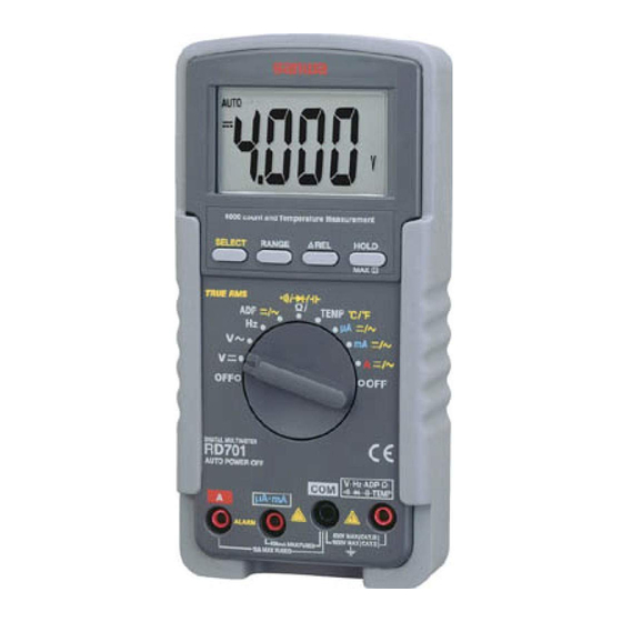
[3] NAME OF FUNCTIONS LCD Display DATA Hold Button / SELECT Button MAX Hold Button RELATIVE Button RANGE Hold Button POWER Switch and Holster FUNCTION Switch V • H z • ADP • Ω • A measuring Terminal • • •TEMP Measuring Terminal µA•mA measuring... -
Page 8: Description Of Functions
[4] DESCRIPTION OF FUNCTIONS 4-1 Function Switch Turn this switch to turn on and off the power and to select the functions of ''V / Hz / ADP / Ω • • • / TEMP / µA / mA / A''. 4-2 Auto Power Off The meter will enter a low power consumption sleep mode automatically to extend battery life after approximately 30 minutes... - Page 9 4-5 Range Hold : RANGE Press the RANGE button momentarily to set the manual range mode then ‘AUTO’ disappears in the display. In manual range mode, press the button again to step through the ranges. To return to the auto mode, press the button for 1 sec. or more then AUTO is shown.
- Page 10 4-10 Words AC Sensing Average RMS: RD700 When measurement is taken by "average", no error is caused as the input signal is shine wave with no distortion. However, if the input waveform is distorted sine cave or non-sinusoidal wave, conversion to root-mean-square values is very difficult, resulting in a large error.
- Page 11 NMRR (Normal Mode Rejection Ratio) NMRR is the DMM's ability to reject unwanted AC noise effect, which causes inaccurate DC measurements. NMRR is typically specified in terms of dB (decibel). This series has a NMRR specification of >60 dB at 50 and 60 Hz, which means a good ability to reject the effect of AC noise in DC measurements.
-
Page 12: Measurement Procedure
[5] MEASUREMENT PROCEDURE 5-1 Start-Up Inspection CAUTION 1. Never use meter if the meter or test leads are damaged or broken. 2. Make sure that the test leads are not cut or otherwise damaged. START Main unit Damaged and test leads damaged? No damaged Check continuty of test... - Page 13 5-2 Voltage measurement / Frequency measurement WARNING 1. Never apply an input signal exceeding the maximum rating input value. 2. Be sure to disconnect the test pins from the circuit when changing the function. 3. Always keep your fingers behind the finger guards on the probe when making measurements.
- Page 14 [DCV Measurement] [ACV Measurement] 5-2-2 Frequency measurement 1) Application Frequency of an AC circuit is measured. 2) Measuring ranges 10.00 Hz to 1.000 MHz (Auto range) 3) Measurement procedure Connect the plug of black test lead to COM measuring input terminal and plug of red test lead to Hz measuring terminal.
- Page 15 5-3 Adapter measurement 1) Applications This function is to measure with optional clamp probe (CL-22 AD and CL33DC), and like. It can measure with this function, if it is the probe like the following. Current clamp probe with 1 mV (Up to 400 mV) output per 1 2) How to use Connect the plug of black test lead or '-' to COM input terminal and plug of red test lead or '+' to ADP input...
- Page 16 [Adapter (ADP) indication example] Clamp Probe Range Probe Output DMM Display Reading value DC 20 A* DC 15 mV DC 0150 1.5 A DC 200 A DC 150 mV DC 1500 150 A CL-22AD AC 20 A* AC 15 mV AC 0150 1.5 A AC 200 A...
- Page 17 5-4 Resistance measurement and Capacitance measurement / Testing Diode / Checking Continuity WARNING Never apply voltage to the input terminals. 5-4-1 Resistance Measurement 1) Applications Resistance of resistors and circuits are measured. 2) Measuring ranges 6 ranges from 400.0 Ω to 40.00 M Ω . 3) Measurement procedure Connect the plug of black test lead to COM input terminal and plug of red test lead to Ω...
- Page 18 5-4-2 Checking Continuity 1) Application Checking the continuity of wiring and selecting wires. 2) How to use Connect the plug of black test lead to COM measuring input terminal and plug of red test lead to measuring terminal. Set the function switch at 'Ω / / / ' and select ' ' with the SELECT button.
- Page 19 5-4-3 Testing Diode 1) Application The quality of diodes is tested. 2) How to use Connect the plug of black test lead to COM measuring input terminal and plug of red test lead to measuring terminal. Set the function switch at 'Ω / / / ' and select ' ' with the SELECT switch.
- Page 20 5-4-4 Capacitance Measurement CAUTION 1. Discharge the capacitance before measurement. 2. Due to the measurement method that this device pours the current into a capacitor the measurement such as the big electrolysis capacitor of a leakage current is not suited in order that the error becomes big.
- Page 21 5-5 Temperature Measurement 1) Application The temperature of outside and water, object is measured. 2) Measuring ranges Range from -20 to 300 Fahrenheit: Range from -4 to 572 3) Measurement procedure Input the -plug to COM input terminal and the +plug to Temp terminal.
- Page 22 5-6 Current Measurement WARNING 1. Never apply voltage to the input terminals. 2. Be sure to make a series connection via load. 3. Do not apply an input exceeding the maximum rated current to the input terminals. 4. Before starting measurement, turn OFF the power switch of the circuit to separate the measuring part and connect the test leads firmly.
- Page 23 3) Measurement procedure Connect the plug of black test lead to COM measuring input terminal and plug of red test lead to µA/mA or A measuring terminal. Set the function switch to 'µA' or 'mA' or 'A' and select either ' or 'AC ' by pressing the SELECT button.
-
Page 24: Maintenance
[6] MAINTENANCE WARNING 1. This section is very important for safety. Read and understand the following instruction fully and maintain your instrument properly. 2. The instrument must be calibrated and inspected at least once a year to maintain the safety and accuracy. 6-1 Maintenance and Inspection 1) Appearance Does falling not damage the appearance? - Page 25 Remove the battery lid screw with a screwdriver. Removed the battery lid. Take out the battery or fuse and replace it with a new one. Attach the battery lid and fix it with the screw. Battery lid screw Battery lid Rear case Fuse 12.5 A/500 V IR: 20 kA...
-
Page 26: After-Sale Service
(1) year from the date of purchase. This warranty policy is valid within the country of purchase only, and applied only to the product purchased from Sanwa authorized agent or distributor. Sanwa reserves the right to inspect all warranty claims to determine the extent to which the warranty policy shall apply. - Page 27 3) Repair after the warranty period has expired: In some cases, repair and transportation cost may become higher than the price of the product. Please contact Sanwa authorized agent / service provider in advance. The minimum retention period of service functional parts is 6 years after the discontinuation of manufacture.
-
Page 28: Specifications
, 80 % R.H. (With battery removed) Altitude: Operating below 2000 m Temperature Coefficient: Nominal 0.15x (specified accuracy)/ @ (0 ), or otherwise specified Power Supply: 9 V battery; NEDA1604, JIS006P or IEC6F22 Sensing: Average Sensing for RD700. True RMS for RD701 — 25 —... - Page 29 3.2 mA Typical Auto Power Off Timing: Idle for 30 minutes Auto Power Off Function Consumption: 300 µA typical for RD700; 360 µA typical for RD701 Dimension: 179(H ) x 87(W ) x 55(D ) mm with holster Mass: 320 g / 460 g with holster...
- Page 31 8-2 Measurement Range and Accuracy Accuracy assurance range: 23±5 & less than 75 % R.H. Function & Range Accuracy Input Impedance Remarks ± 400.0 mV (0.3 %rdg + 4 dgt) 1000 M Ω NMRR: 4.000 V >50 dB@50/60 Hz 10 M Ω...
- Page 32 Input Impedance Remarks ± ( 0.3 %rdg + 4 dgt) 1000 M Ω 30 pF RD700: 50 Hz~500 Hz ± (1.5 %rdg + 5 dgt) nominal RD701: 50 Hz~3 kHz 3) The accuracy of the sensor is not included. Accuracy calculation For example…...
- Page 33 MEMO — 36 —...
- Page 34 SANWA ELECTRIC INSTRUMENT CO.,LTD. Dempa Bldg,Sotokanda2-Chome Chiyoda-Ku,Tokyo,Japan 06-1404 2040 6010...
Need help?
Do you have a question about the RD700 and is the answer not in the manual?
Questions and answers